For two decades, I've specified, installed, and cursed inductive proximity sensors in environments ranging from pristine clean rooms to foundry floors caked in conductive dust. Forget the datasheet platitudes. Here’s what you won’t find in the glossy brochures.
Experience Correction: The Gaps Between Spec and Reality
The nominal sensing distance (Sn) is a laboratory fantasy. In practice, three factors eviscerate it. First, target material. While the correction factor for stainless steel (typically 0.7-0.9) is known, few account for the dramatic drop with hot-rolled steel versus cold-rolled due to surface scale and permeability variance. I've measured a 35% reduction in Sn on scaled HR plate versus its CR counterpart. Second, voltage drop. The "10-30V DC" operating range suggests robustness. However, on long cable runs in high-temperature areas, voltage at the sensor can sag below 10V, causing erratic switching. I've traced countless "ghost signals" to a sensor receiving 9.2V at the terminal, not the 12V at the panel. Third, temperature drift. The stated operating temperature, say -25°C to 70°C, assumes a constant Sn. Reality: sensing distance can shift by up to ±10% across this range. In a freezer application at -20°C, a sensor calibrated at room temperature failed to detect pallets until we derated its effective Sn by 15%.
Boundary Conditions: Where They Will Fail You
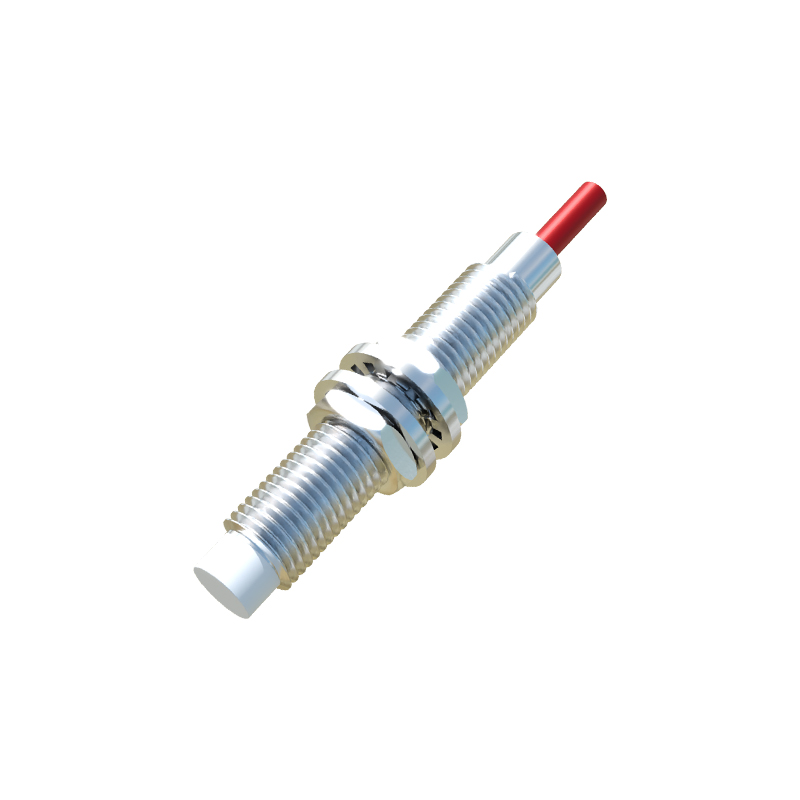
These sensors are not universal detectors. Deploy them in the following conditions at your peril.
1. Submerged in Conductive Coolants: While many boast IP67/IP68 ratings, this is for water. Immersion in conductive fluids like water-soluble machining coolant creates a capacitive bridge across the sensing face. This can cause the oscillator to remain damped, locking the output "ON" even with no target present. I've seen this cause catastrophic machine collisions.
2. Extreme Electromagnetic Interference (EMI) Fields: Datasheets list a modest 30V/m RF immunity. Position one within 2 meters of a 400A AC arc welder's ground cable, and the pulsed magnetic field will induce false pulses in the output circuit, regardless of shielding. The solution isn't a better sensor; it's relocation.
3. Detection of Fine, Non-Metallic Powders: A common "clever" application is monitoring powder levels in a hopper. For most organic powders, this fails. The dielectric constant is too low to sufficiently damp the oscillator. You'll get a detection shift of maybe 1mm for a full hopper versus empty—a change indistinguishable from temperature noise. It's a worthless installation.
4. High-Speed Counting of Small, Irregular Targets: The 5kHz switching frequency seems ample. But for counting stampings with burrs or twisted metal scraps, the issue is repeatability. A burr passing at 3 o'clock might trigger, while at 9 o'clock it won't. The effective sensing field is not a perfect cylinder; its edges are inconsistent. Rely on this for accurate count-based batching, and your recipe consistency is gone.
Counter-Intuitive Conclusions: Data-Driven Heresies
1. A "Less Sensitive" Sensor is Often More Reliable: In high-vibration environments with metallic debris, a standard 8mm range sensor will be triggered by flying swarf, causing faults. Switching to a "reduced range" or "factor 1" sensor (designed for non-ferrous metals) cuts the Sn to perhaps 2mm. This creates a much steeper field gradient, making it immune to debris but still perfectly capable of detecting the solid, repeatably positioned target. Stability increases dramatically.
2. Shielding Can Increase Interference in Certain Layouts: Barrel sensors come in shielded (flush-mountable) and unshielded versions. The dogma: always use shielded in metallic mounts. However, in a dense panel with multiple sensors side-by-side, the shielded sensor's lateral field is minimal, preventing crosstalk. But if you have a single sensor near a large, moving, grounded metal structure (like a machine column), the unshielded sensor's wider field can see this structure as a target, causing falsing. Here, a shielded sensor, with its tightly focused forward field, is ironically less susceptible to this peripheral interference.
3. The Most Critical Parameter Isn't Sn or Frequency; It's Hysteresis: Hysteresis—the difference between the switch-on and switch-off point—is a footnote. In dynamic systems, it's everything.