Forget the pristine datasheets and lab demos. After twenty years of deploying square proximity sensors in everything from foundries to food processing, I’m here to cut through the noise. The real value isn't in the nominal specs; it's in knowing where those specs lie and how they fail.
Experience Correction: The Gritty Reality of "Standard" Specs
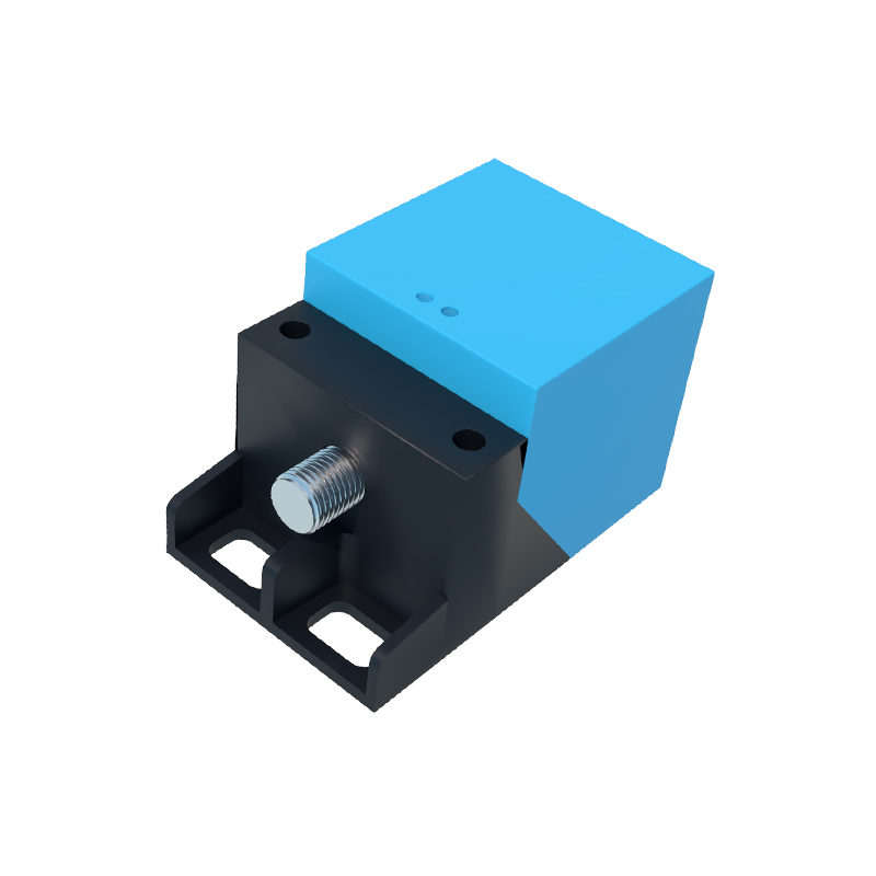
The advertised sensing distance is a fantasy in the real world. A sensor rated for 15mm on mild steel will see that distance drop by 40-60% on 304 stainless steel. On aluminum? Expect a 60-70% reduction. The industry's dirty secret is that the standard "Fe360" calibration is a best-case scenario, rarely encountered. Furthermore, the "operating temperature" range is a steady-state figure. In a stamping press environment with hydraulic oil splash, thermal shock can cause internal condensation, leading to intermittent failure well within the stated temperature band. I've logged failures on sensors rated for 85°C when ambient was only 50°C, but rapid cycling and oil mist created a microclimate that breached the housing's seal integrity. Rely on the IP rating? IP67 means nothing if a high-pressure wash hits a fatigued cable gland at the wrong angle. The failure point is almost never the sensing face; it's the cable entry, the housing seam, or the connector.
Boundary Conditions: When to Walk Away
Do not use standard inductive square sensors for any of the following, regardless of marketing claims:
1. Fine, Non-Ferrous Metal Chips or Swarf: In CNC machining of brass or aluminum, a cloud of conductive dust will settle on the face, effectively "shielding" the sensor. It will latch on or off and require physical cleaning. Capacitive models are equally fooled by moisture and material buildup.
2. High-Speed Sensing of Small, Irregular Targets: The "switching frequency" assumes a clean, full-face approach. Detecting the teeth of a small, fast-moving gear or a chain link often fails because the target's dwell time in the electromagnetic field is insufficient for the sensor's damping circuit to register a stable signal. You get chatter. The solution is often a sensor with a much shorter nominal range than the application seems to require, forcing a stronger, faster field collapse.
3. Extreme Electromagnetic Noise Environments: Near large VFDs (Variable Frequency Drives) or arc welders, the common-mode noise rejection of standard DC sensors is inadequate. I've seen sensors trigger from three meters away when a 1000-amp weld started. The fix isn't always shielding; sometimes you must switch to a fully analog current-output sensor and set thresholds in the PLC, abandoning the neat digital switch.
4. Precision Positioning of Multi-Material Assemblies: Sensing a plastic component with a tiny embedded metal slug. The effective sensing point will shift based on the plastic's dielectric constant and the slug's exact position within the field. Your repeatability can vary by ±2mm, which is catastrophic for robotic insertion.
Counter-Intuitive Conclusion: Sometimes, Less Sensing is More
The most reliable, bulletproof installation often involves intentionally degrading the sensor's performance. Here’s the data-backed insight: A sensor operating at 80-90% of its rated distance on a perfect target is far more stable and resistant to environmental variables than one pushed to 100%. The electromagnetic field at the extreme edge of the sensing range is weak and diffuse, easily influenced by temperature drift, supply voltage fluctuations, and nearby metal. By mechanically mounting the sensor closer to the target—effectively "over-sensing"—you operate in the steep, stable, high-flux portion of the field curve. In one automotive body-in-white application, this simple practice reduced false triggers from thermal expansion by over 95%. The cost was a slightly more complex bracket. The reward was near-perfect uptime. Another non-intuitive truth: In high-vibration settings, a lower response frequency (e.g., 500 Hz vs. 2 kHz) can be more reliable. The higher-frequency sensor's circuitry is more sensitive to the micro-vibrations that modulate the field, causing output ripple. Slowing it down adds inherent damping. Don't chase the headline spec; engineer for the stability margin.