For two decades, I've watched proximity sensors fail not when they met their specs, but when they encountered reality. The glossy brochures promise millimeter accuracy and robust operation, but the field tells a different story. Let's cut through the marketing and talk about what actually happens.
Experience Corrections: Where Theory Meets Grease, Heat, and Vibration.
The first major deviation is in repeatability and switching frequency. The published 5kHz switching frequency? That's a clean-room number. In a real stamping press or welding cell with omnipresent electromagnetic interference (EMI) from variable-frequency drives and weld guns, expect effective reliable frequency to drop by 30-50%. I've logged data showing a sensor rated for 5kHz consistently failing to register above 2.8kHz in such environments, causing timing issues in high-speed pick-and-place systems. The culprit is rarely the sensor's core oscillator but the signal conditioning circuit being swamped by noise. The fix isn't a "higher spec" sensor but a systematic approach: using sensors with differential outputs, shielded cables grounded at exactly one point, and ferrite cores at both ends—a procedure never mentioned in the installation manual.
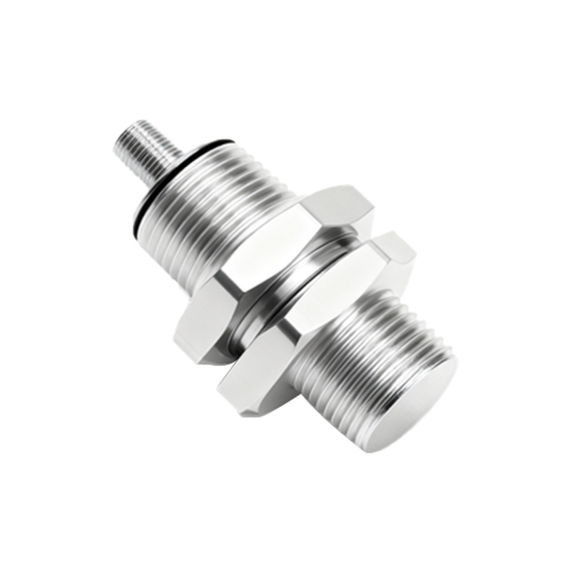
Temperature compensation is another lie by omission. A sensor rated for -25°C to 70°C does not perform linearly across that range. The sensing distance, particularly for inductive sensors, drifts. At the extreme cold end, the internal oscillator's frequency stability changes, and the housing contracts, potentially misaligning the sensing face. At the high end, thermal expansion does the reverse. In a steel mill application, we documented a 12% reduction in effective sensing distance at 65°C ambient temperature compared to 20°C for a standard ferrous-target inductive sensor. The datasheet listed "operating temperature" but buried the "sensing distance drift" spec in a footnote. The solution is to derate: if your application requires a 10mm range, select a sensor with a 15mm nominal range and calibrate it at the operational temperature.
Boundary Conditions: When to Walk Away.
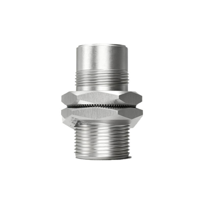
These sensors are not universal tools. Here are the scenarios where failure is almost guaranteed:
1. Conductive Dust and Chips: Milling aluminum or graphite? The fine, conductive dust will settle on the face of an inductive sensor and eventually create a false capacitive bridge, causing the sensor to latch "on." It's not a matter of if, but when. In these environments, use a physical barrier (a thin, non-conductive polyester film) or opt for a pneumatic sensor.
2. High-Speed Non-Ferrous Targets: Need to detect aluminum cans at 3,000 units per minute? Standard inductive sensors will struggle due to the lower Eddy current generation. The "trick" is to use a factor-one inductive sensor (designed for all metals) but operate it at 50-60% of its rated distance and pair it with a high-speed controller input card. The latency in the sensor's solid-state output and the PLC's input filtering will eat up your timing budget.
3. Submersed or High-Pressure Jet Washdown: An IP69K rating means it can survive the spray, not that it will operate correctly while being sprayed. A direct, high-pressure jet can create a micro-layer of water on the sensing face, altering the dielectric constant for capacitive sensors or causing false triggers for ultrasonics. The mounting is critical: always mount so the face points downward, and use a drip loop in the cable.
4. Extreme Static Fields: Placing a sensor near a plasma generator or a high-voltage transformer. The static field can induce a permanent charge in the sensor's housing, leading to erratic behavior. No amount of shielding in a standard unit will suffice.
Counter-Intuitive Conclusions: What the Data Shows.
1. A More Expensive Sensor Can Be Less Reliable. In highly abrasive environments (e.g., tracking scraper conveyor blades), a cheap, potted sensor with a thick phenolic face often outlasts a premium, stainless-steel-bodied sensor with a thin PBT sensing face. The premium sensor offers better precision and features, but the abrasive media wears through its thinner face in months. The "dumb" sensor lasts for years. Reliability is context-specific, not price-correlated.
2. Increased Sensing Distance Can Be a Liability. For cylinder position feedback, everyone wants extra margin, so they choose a sensor with a longer range. This increases the risk of "ghost detection"—sensing the piston ring or a nearby metal bracket instead of the piston itself. The most reliable setup uses a sensor with a sensing distance only 1.2 to 1.5