Proximity sensors are fundamental components in modern industrial automation, providing non-contact detection of objects. Among the various output configurations, the NPN type is widely used, particularly in regions like Europe and Asia. Understanding the NPN proximity sensor wiring diagram is crucial for correct installation, troubleshooting, and ensuring system reliability. This guide breaks down the schematic, explains the underlying electrical principle, and outlines practical connection steps.
At its core, an NPN proximity sensor is a solid-state electronic device. The term "NPN" refers to the type of transistor used in its output switching circuit. An NPN transistor allows current to flow from the load to the sensor's output terminal when activated. This is key to understanding the wiring: in a typical NPN configuration, the sensor acts as a sinking device. It connects the load to ground (0V) when a target is detected.
A standard NPN proximity sensor has three wires, often color-coded as Brown, Blue, and Black. The Brown wire is connected to the positive supply voltage (typically +12V or +24V DC). The Blue wire is connected to the common ground (0V). The Black wire is the output signal wire. In the NPN normally-open (NO) configuration, when no target is present, the Black wire is electrically disconnected (open circuit). When a target enters the sensing range, the internal NPN transistor switches on, connecting the Black output wire internally to the Blue wire (ground). This creates a path to ground for the connected load.

The wiring diagram visually represents this. The load (e.g., a PLC input, relay coil, or indicator lamp) is connected between the positive supply voltage and the sensor's Black output wire. When the sensor activates, it "sinks" the current from the load to ground, completing the circuit and energizing the load. It is vital to note that the load must be present for the circuit to function; the sensor itself does not supply power but provides a switched path to ground.
Contrasting this with a PNP sensor clarifies the concept. A PNP sensor sources current; its output wire provides positive voltage when activated. With an NPN sensor, the switching is on the negative/ground side. This distinction is critical for compatibility with control devices. Many programmable logic controllers (PLCs) have input cards designed specifically for either sinking (NPN) or sourcing (PNP) sensors. Connecting an NPN sensor to a sinking input is straightforward. The PLC input point is internally connected to positive voltage, and the sensor connects it to ground when triggered.
For practical wiring, follow these steps. First, identify the sensor's specifications and wiring diagram from its datasheet. Second, ensure a stable DC power supply matches the sensor's voltage rating. Connect the Brown wire to the positive terminal and the Blue wire to the negative terminal of the power supply. Third, connect one side of your load (e.g., one terminal of a relay coil) to the same positive supply. Connect the other side of the load to the sensor's Black output wire. When the sensor detects an object, current will flow from the positive supply, through the load, through the activated sensor (Black to Blue), and back to the power supply negative, activating the load.
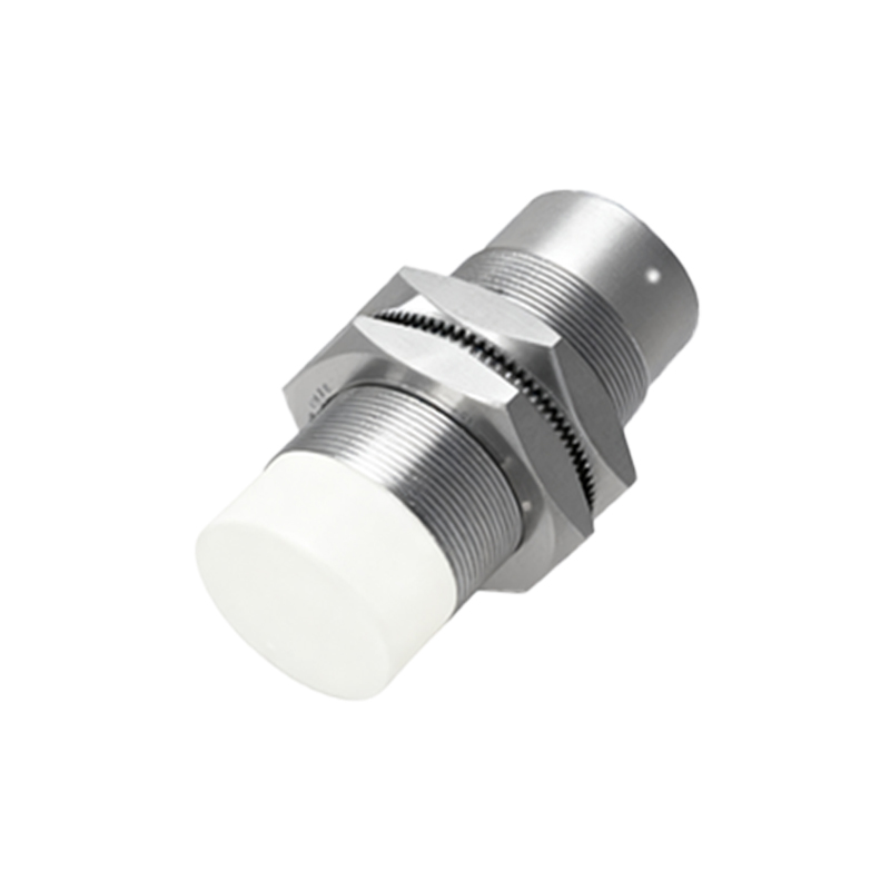
Common issues arise from incorrect wiring. If the sensor's indicator LED lights but the load doesn't activate, the load might be connected incorrectly or be faulty. Verify that the load is placed between the positive supply and the Black wire. If the sensor does not power on, check the polarity of the Brown and Blue connections. Never connect the sensor to an AC power source unless explicitly rated for it. Always implement protective measures like fuses and ensure proper grounding to shield against electrical noise, which can cause false triggering in sensitive environments.
In summary, the NPN proximity sensor wiring diagram illustrates a sinking output circuit. The sensor closes a path to ground for the connected load upon detection. Mastery of this diagram—recognizing the Brown (positive), Blue (ground/negative), and Black (switched output) wires—enables seamless integration into control systems. This knowledge ensures not only functional installations but also forms the basis for diagnosing faults and optimizing automated processes for efficiency and safety. Always consult the manufacturer's documentation for model-specific details, as wire colors and functions can occasionally vary.