Linear proximity sensors are fundamental components in modern industrial automation, robotics, and precision measurement systems. At the heart of their operation lies the critical parameter of output voltage. Understanding this voltage signal—its source, behavior, and interpretation—is essential for effective system integration, calibration, and maintenance. Unlike simple on/off proximity switches, linear sensors provide a continuous analog voltage output that is directly proportional to the distance between the sensor's face and the target object.
The core working principle dictates the voltage relationship. Inductive linear proximity sensors, commonly used for detecting metals, generate an electromagnetic field. When a metallic target enters this field, eddy currents are induced, which dampen the field's oscillation. An internal circuit measures this damping and converts it into a linearly changing DC voltage. Typically, these sensors operate on a DC supply voltage, often 12V or 24V DC. The output is a ratiometric analog signal, usually in the range of 0-10V or 1-10V. For instance, in a 0-10V sensor with a sensing range of 2mm to 10mm, 0V might correspond to a 10mm distance (or vice-versa, depending on configuration), and 10V would correspond to the 2mm point. The voltage changes smoothly and linearly between these extremes, providing a precise measurement of position.
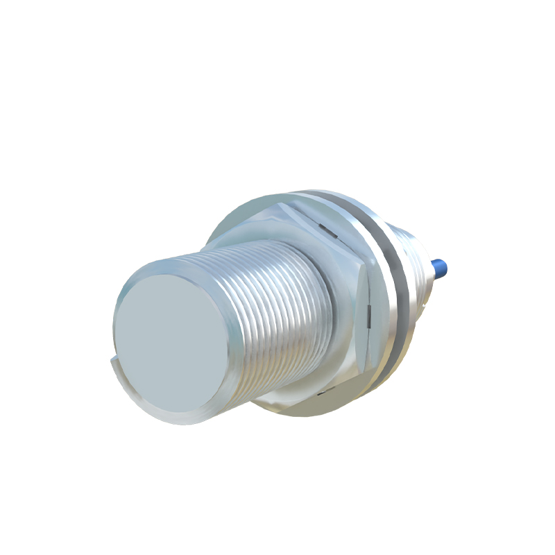
Capacitive linear sensors, used for non-metallic materials, function similarly but rely on changes in capacitance. The presence of any material alters the dielectric constant, changing the capacitance in the sensor's oscillator circuit. This change is subsequently translated into a proportional output voltage. The voltage characteristic curve—plotting distance versus output voltage—is the key datasheet specification. Engineers must carefully examine this curve to understand the linear range, saturation points, and any inherent non-linearity at the range extremes.
Accurate voltage measurement is paramount. A high-quality digital multimeter (DMM) is the basic tool, but for dynamic measurements or system analysis, an oscilloscope is indispensable. It can reveal noise, ripple, or instability in the output signal that a DMM might average out. When measuring, it is crucial to ensure the sensor is properly powered and the target is moving within its specified linear range. The load impedance of the measuring device or the connected controller (like a PLC analog input module) must be considered. If the input impedance is too low, it can load the sensor's output circuit, causing a voltage drop and significant measurement error. Most sensor datasheets specify a minimum load impedance, such as 5 kΩ, to guarantee proper performance.
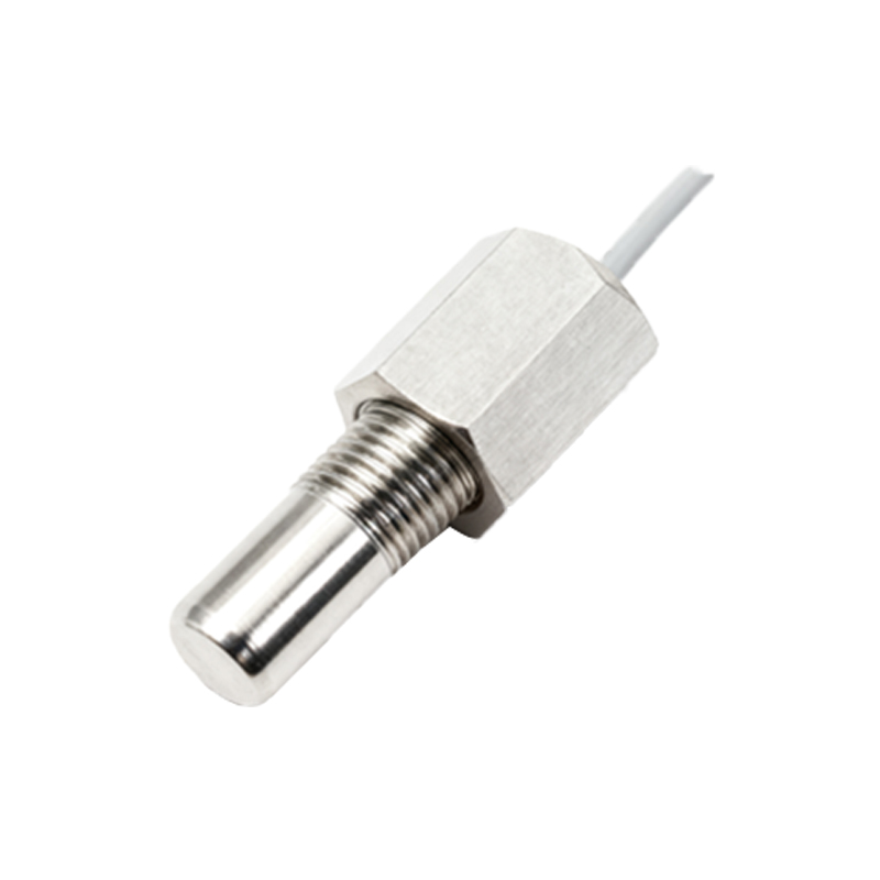
Common voltage-related issues provide clear diagnostic clues. A zero-voltage output, despite a confirmed power supply, often points to a wiring fault, a damaged sensor, or the target being completely outside the sensing range. An output stuck at the supply voltage (e.g., constant 12V) typically indicates a short circuit in the sensor's output transistor or severe internal damage. Erratic or noisy voltage readings are frequent problems. Sources of electrical noise include nearby variable frequency drives (VFDs), welding equipment, or long, unshielded cables running parallel to power lines. Solutions involve using shielded cables, grounding the shield properly at one end, installing ferrite cores, or relocating cables away from noise sources. Non-linear output, where the voltage does not change proportionally with distance, can stem from using an incorrect target material (e.g., aluminum instead of steel for an inductive sensor), a target that is too small, or physical damage to the sensor face.
For optimal performance, calibration against a known standard, such as precision gauge blocks, is recommended. This process verifies the voltage-distance relationship. Furthermore, understanding the sensor's resolution—the smallest distance change it can detect, reflected as a minute voltage change—is vital for high-precision applications. Environmental factors like temperature swings can also cause a zero-point drift or span drift, manifesting as a gradual shift in the output voltage for a fixed distance. Selecting sensors with good temperature compensation is critical for stable environments.
In summary, the output voltage of a linear proximity sensor is its language. By meticulously measuring this signal, interpreting its values against the datasheet curve, and systematically troubleshooting deviations, technicians and engineers can ensure these critical devices deliver reliable, accurate, and continuous feedback for automated systems. Proper installation, shielding, and load matching are not optional steps but fundamental requirements for translating physical position into a clean, usable voltage signal.