Proximity sensors are fundamental components in modern automation, playing a crucial role in detecting the presence or absence of an object without physical contact. Understanding their electrical wiring is essential for proper installation, troubleshooting, and integration into control systems. This guide explains the standard electrical diagrams for common proximity sensor types.
At its core, an electrical diagram for a proximity sensor details how to connect its wires to a power supply and a load, typically a programmable logic controller (PLC) input or a relay. Most industrial proximity sensors have three or four wires, categorized by their function: power supply, ground, output signal, and sometimes a separate output common.
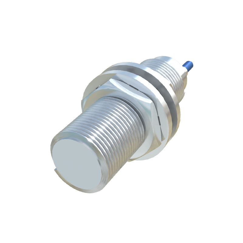
The most prevalent type is the 3-wire DC sensor. It comes in two output configurations: NPN (sinking) and PNP (sourcing). This terminology refers to the type of transistor used in the sensor's output stage and determines how current flows.
In a standard PNP proximity sensor wiring diagram, you will find three wires: brown, blue, and black. The brown wire connects to the positive DC supply voltage (e.g., +24V). The blue wire connects to the negative DC supply (0V or common). The black wire is the output signal line. When the sensor detects a target, it switches the black wire, connecting it internally to the positive supply (brown). This "sources" current to the load. The load (like a PLC input) is then connected between the black wire and the negative supply. Thus, the PNP sensor provides a positive signal upon detection.
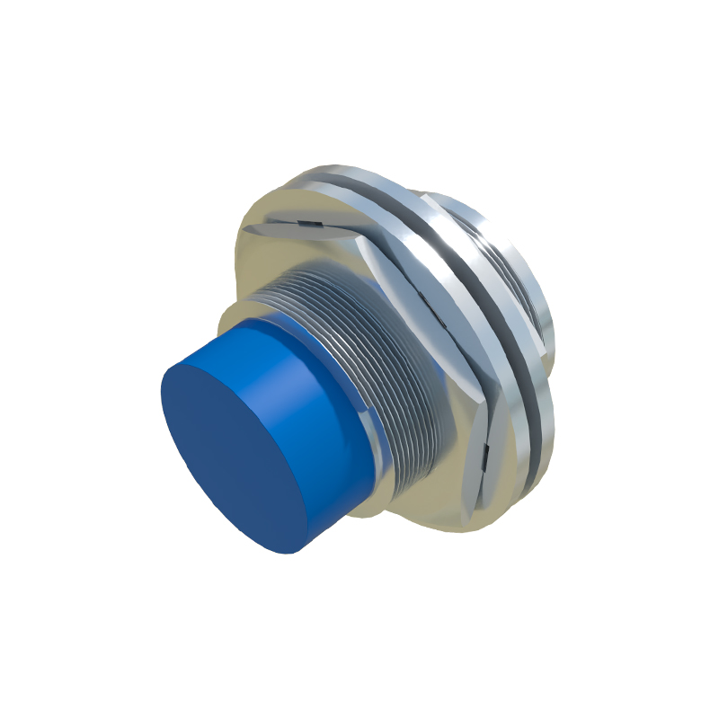
Conversely, a standard NPN proximity sensor wiring diagram also uses brown (positive), blue (negative/0V), and black (output). The key difference is in the output switching. When active, an NPN sensor connects the black output wire internally to the negative supply (blue). It "sinks" current from the load. Here, the load must be connected between the positive supply and the black wire. The NPN sensor provides a path to ground when activated.

Choosing between PNP and NPN often depends on the control system's input module design. Many PLCs in Europe and commonly in sinking input modules use PNP sensors. NPN sensors are frequently used in Asia and with sourcing input modules.
For 4-wire DC sensors, the diagram includes an additional wire, usually white. These sensors offer both a Normally Open (NO) and a Normally Closed (NC) output from the same device. The typical wiring is brown (+V), blue (0V), black (NO output), and white (NC output). The NO output is open when no target is present and closes (switches) when detected. The NC output does the opposite: it is closed at rest and opens upon detection. This provides flexibility for safety or logic requirements.
2-wire AC/DC sensors simplify wiring but have considerations. They connect in series with the load and the power supply, much like a mechanical switch. There is no polarity for AC types. However, they have a residual voltage drop when on and a small leakage current when off, which must be compatible with the connected load's sensitivity.
When interpreting or creating a proximity sensor electrical diagram, always prioritize the manufacturer's datasheet. Wire colors can vary, though brown/blue/black is an international common standard (IEC). Key specifications to cross-reference include operating voltage range, output current capacity, and switching frequency.
A typical connection procedure involves: 1) Disconnecting all power. 2) Connecting the supply wires (brown/+V, blue/0V) to a stable power source within the sensor's rated voltage. 3) Connecting the output wire (black) to the intended load. 4) Ensuring the load is completed to the opposite power rail as required by the sensor type (PNP vs. NPN). 5) Securing connections and checking for loose strands. 6) Applying power and testing sensor operation with a target.
Common wiring errors include confusing PNP and NPN connections, which prevents the load from activating, or connecting the load incorrectly in series with the power supply instead of in the correct loop. Using an insufficient power supply or overloading the sensor's output can lead to failure. Always ensure the sensor body (especially metal ones) is properly grounded if specified.
In summary, a proximity sensor electrical diagram is a straightforward map for connectivity. Recognizing the difference between PNP (sourcing) and NPN (sinking) outputs is the most critical step for successful implementation. By following the color codes and schematic logic, technicians can reliably integrate these non-contact detection devices into diverse industrial applications, from conveyor systems to robotic cells, ensuring precise and reliable operation.
SEO