Building your own metal proximity sensor can be a rewarding and educational electronics project. It allows you to understand the fundamental principles of sensing technology while creating a functional device for applications like security systems, automation, or simple detection tasks. This guide will walk you through creating a basic inductive proximity sensor capable of detecting nearby metal objects without physical contact.
The core principle behind a simple DIY metal proximity sensor is electromagnetic induction. When a metal object enters the alternating magnetic field generated by a coil, eddy currents are induced in the metal. This changes the coil's inductance and the overall behavior of the circuit, which can be detected and used to trigger a signal. For this project, we will construct an oscillator-based sensor, a common and effective design.
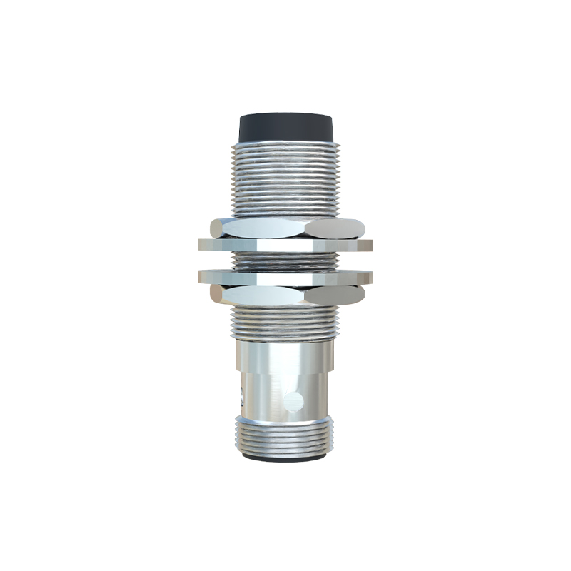
First, gather the necessary components. You will need a coil (an inductor), which is the heart of the sensor. You can wind your own coil using enameled copper wire around a ferrite core or a simple plastic spool; approximately 50-100 turns will work for a start. Other essential components include a transistor (a general-purpose NPN transistor like BC547 or 2N2222), several resistors (values like 10kΩ, 1kΩ), capacitors (e.g., 100nF, 10nF), an LED for visual indication, and a power source, typically a 5V to 12V DC supply. A breadboard, jumper wires, and a multimeter are also required for prototyping and testing.
Begin by constructing the oscillator circuit. Place the transistor on the breadboard. Connect a resistor (e.g., 10kΩ) from the positive supply rail to the base of the transistor. Connect one lead of your hand-wound coil to the collector of the transistor. The other lead of the coil goes to the positive supply rail through another resistor (e.g., 1kΩ). Connect the emitter of the transistor directly to the ground (negative rail). Now, add a capacitor (e.g., 100nF) between the collector and the base of the transistor. This capacitor, along with the coil, forms the resonant tank circuit that determines the oscillator's frequency. The circuit should now oscillate, generating a high-frequency alternating magnetic field around the coil.
The next stage is the detection circuit. We need to monitor the oscillator's amplitude. When a metal object approaches the coil, the eddy currents dampen the oscillation, reducing its amplitude. To detect this change, add a simple diode detector. Connect a small signal diode (like 1N4148) from the collector of the transistor to a new node. The cathode of the diode should point away from the transistor. From this node, connect a capacitor (e.g., 10nF) to ground. This capacitor will charge to the peak voltage of the oscillations. Also, connect a high-value resistor (e.g., 1MΩ) from this node to ground to slowly discharge the capacitor when the oscillation stops.
Finally, add an output stage. The voltage across the detection capacitor now represents the oscillation strength. We can use another transistor as a switch to drive an LED. Connect the base of a second NPN transistor to the detection node through a current-limiting resistor (e.g., 100kΩ). Connect the emitter of this second transistor to ground. Connect an LED and a current-limiting resistor (e.g., 330Ω) in series from the positive supply to the collector of this second transistor. In the normal state (oscillation strong, no metal present), the detection node voltage is high, keeping the second transistor ON and the LED OFF. When metal approaches, the oscillation dampens, the detection node voltage drops, turning the second transistor OFF, which allows current to flow and lights up the LED.
Once the circuit is assembled on the breadboard, apply power. You should observe the LED is off. Now, bring a piece of metal, like a screwdriver or a coin, close to the coil. The LED should light up, indicating detection. The sensitivity depends on factors like the number of coil turns, the oscillator frequency, and the size of the metal object. You can experiment by adjusting the number of coil turns or the value of the feedback capacitor to change the sensing range, which is typically a few millimeters for a simple coil.
For a more stable and reliable sensor, consider moving the circuit from the breadboard to a perforated board or designing a custom PCB. Shielding the coil from external electrical noise can improve performance. You can also replace the LED with a relay module or connect the output to a microcontroller like an Arduino for more advanced logic and integration into larger projects. This basic design provides a solid foundation. By understanding and modifying this circuit, you can tailor the sensor's range, response time, and output signal to suit specific needs, opening doors