In the world of industrial automation and control systems, clear and immediate communication is paramount. Proximity switch sensors, as vital non-contact detection devices, rely heavily on standardized symbols and icons for representation in technical drawings, electrical schematics, and Human-Machine Interface (HMI) screens. Understanding these "proximity switch sensor icons" is not just a matter of reading a diagram; it's the language of efficient design, troubleshooting, and safety.
At its core, an icon for a proximity sensor must convey its fundamental operating principle without ambiguity. Unlike a mechanical limit switch with a lever arm, a proximity sensor detects an object's presence without physical contact. This key characteristic is universally symbolized. The most common base symbol, as seen in IEC and ANSI standards, is a diamond shape within a square or circle. The diamond signifies the active sensing face or field. This simple geometric form is the foundational "noun" in this symbolic language.
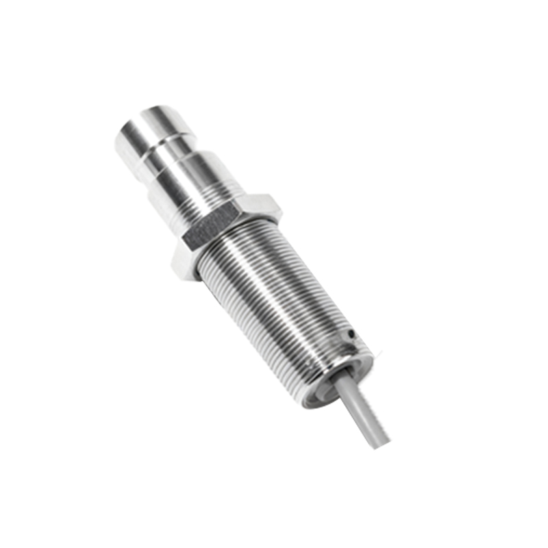
However, the true specificity comes from modifiers and internal markings that answer the critical question: How does it sense? This is where icons diverge based on the underlying technology.
Inductive Proximity Sensors: Icons for these sensors, which detect metallic objects (primarily ferrous metals), typically feature a coil symbol or a series of curved lines within or adjacent to the diamond. This represents the electromagnetic field generated by the sensor's oscillator circuit. A common variant includes the target symbol—a simple rectangle or line—placed just outside the diamond, indicating the metallic object entering the detection field.
Capacitive Proximity Sensors: These sensors can detect both metallic and non-metallic materials (plastics, wood, liquids) by sensing changes in capacitance. Their icons often incorporate two parallel lines or plates near the sensing diamond, symbolizing the capacitor plates formed between the sensor face, the target, and the ground.
Ultrasonic Proximity Sensors: Representing sensors that use sound waves, their icons frequently include stylized representations of sound waves—concentric arcs emanating from the diamond or a "U" shape symbolizing the transducer. Arrows might indicate the transmission and reception of the ultrasonic pulse.
Photoelectric Sensors: While sometimes categorized separately, their proximity-mode function (diffuse or retro-reflective) has distinct icons. These are almost always depicted with a diamond or circle from which a fan of diverging lines (light beams) emanates, often with a separate parallel line representing the reflected beam returning to the receiver.
Beyond the sensing technology, the icon must communicate the electrical output type and switching function. This is usually denoted by the standard symbols for a switch placed in-line with the sensor symbol. The nature of this switch symbol defines the output logic:
A normally open (NO) contact symbol (like a break in a line that closes upon detection) indicates that the sensor's output circuit closes when a target is present. This is often labeled "PNP" or "Sourcing" in context.
A normally closed (NC) contact symbol (a closed line that opens upon detection) shows the circuit opens when a target is detected.
Some advanced icons incorporate the simplified symbols for a transistor to directly denote a solid-state PNP or NPN output.
On wiring diagrams and PLC (Programmable Logic Controller) layouts, the icon is integrated into a full schematic. It will be connected to terminals for power supply (typically +V and 0V DC) and the load (the output wire going to a PLC input or a relay). A clear icon allows an engineer to instantly identify, for example, a "three-wire, DC-powered, inductive proximity sensor with a PNP normally open output."
On HMI screens and control panels, the icons become more pictorial but retain their symbolic essence. They may be color-coded (green for normal, red for fault or activation) and are often dynamic, changing state when the sensor is triggered. This provides operators with real-time, at-a-glance understanding of machine status—is the part in position? Is the tank level adequate? Is the safety guard closed?
The power of standardization cannot be overstated. Whether it's the IEC 60617 database or ANSI Y32.2 norms, these standards ensure that a technician in Germany, an OEM in Japan, and an end-user in the United States all interpret the same icon identically. This reduces errors, speeds up commissioning and maintenance, and enhances global collaboration.
In conclusion, proximity switch sensor icons are far more than simple pictures. They are a dense, information-rich visual code. Mastering this code—recognizing the diamond, interpreting the technology modifiers, and understanding the output switch symbology—is an essential skill for anyone involved in automation. It bridges the gap between the physical sensor on the machine and its abstract representation in documentation and software,