Understanding the Role of a Series Resistor in Photoelectric Sensors
In industrial applications, a photoelectric sensor often requires a series resistor to limit current when connected to a load or controller input. This resistor protects the sensor’s output transistor from excessive current, which can cause thermal damage or premature failure. For instance, in a typical NPN or PNP output sensor, the series resistor ensures the output voltage stays within the acceptable range for the receiving device, such as a PLC or relay. The value of this resistor is not arbitrary; it must be calculated based on the sensor’s output characteristics and the load requirements.
Key Parameters for Calculation
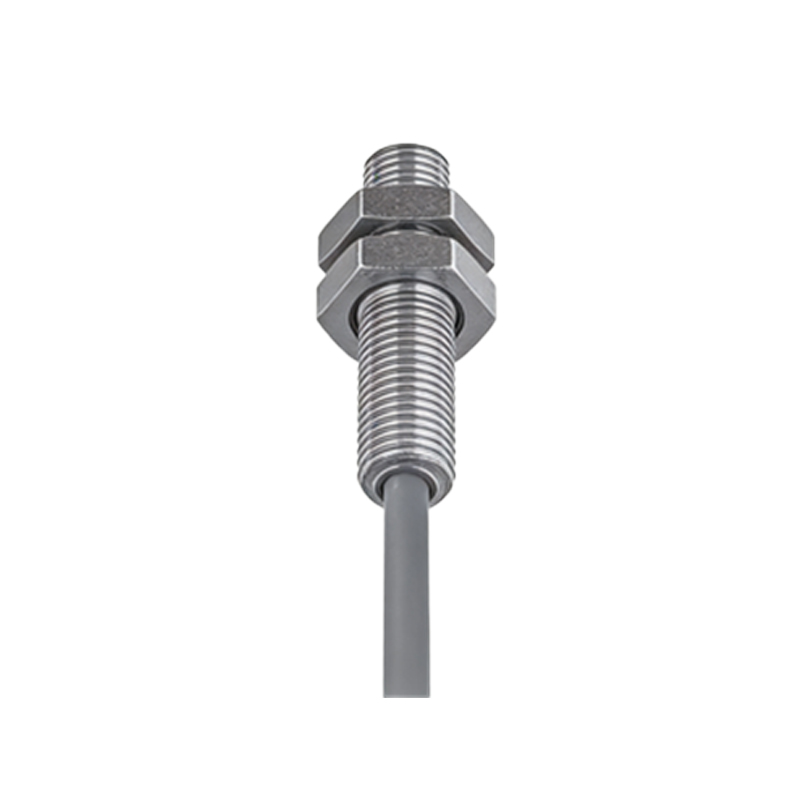
To determine the correct series resistor, you need three main parameters: the sensor’s supply voltage (Vcc), the load resistance (R_load), and the maximum permissible current through the sensor’s output transistor (I_max). Most photoelectric sensors specify I_max in their datasheets, often around 100 mA to 200 mA for standard models. Additionally, consider the forward voltage drop of the sensor’s output stage, typically less than 1.5 V. For example, if Vcc is 24 V and I_max is 100 mA, the total resistance in the circuit must be at least R_total = Vcc / I_max = 240 ohms. Subtract the load resistance from this to find the series resistor value.
Practical Example for a 24V DC System
Assume you have a photoelectric sensor with a 24 V DC supply and a PLC input that has an internal resistance of 10 kΩ. The sensor’s datasheet states its output can handle up to 100 mA. To protect the sensor, you want to limit the current to 50 mA for safety. Calculate the total resistance needed: R_total = 24 V / 0.05 A = 480 ohms. Since the load resistance (10 kΩ) is much larger, it can be ignored in parallel calculations, but in series circuits, the series resistor should be approximately 480 ohms. However, for standard availability, use a 470-ohm resistor. This ensures the current stays below 50 mA even under worst-case conditions.
Common Pitfalls and Troubleshooting
A frequent mistake is using too high a resistor value, which can drop the voltage below the load’s minimum operating threshold. For example, with a 1 kΩ series resistor and a 10 kΩ load, the voltage across the load might drop to about 21.8 V, which is acceptable. But if the resistor is 5 kΩ, the voltage drops to 16 V, potentially causing the PLC input to not detect a high signal. Always verify the load’s voltage range. Another issue is oversizing the resistor for thermal dissipation; a 470-ohm resistor at 50 mA dissipates just 1.175 W, so a 2 W rated resistor is safe.
Recommended Practices for Industrial Settings
In practice, for standard 24 V DC photoelectric sensors, a series resistor of 470 ohms to 1 kΩ is common, with a power rating of at least 1 W. For sensors with a 12 V supply, reduce the resistor to around 220 ohms. Always test the circuit with a multimeter to ensure the voltage at the load input is within its logic high threshold (e.g., >15 V for 24 V systems). Additionally, use resistors with a tolerance of ±5% to maintain precision. If the sensor is used in noisy environments, consider adding a capacitor in parallel with the load to filter transients, but this does not affect the resistor calculation.