Understanding the Fundamentals of Photoelectric Sensor Response
Photoelectric sensors are critical components in modern industrial automation, used for object detection, positioning, and counting. Their response time directly impacts system throughput and accuracy. The response time is defined as the interval between the sensor detecting an object and outputting a signal. Key factors include the sensor's operating principle (through-beam, retro-reflective, or diffuse), ambient light conditions, and target surface characteristics. To enhance response, engineers must first analyze these base parameters. For instance, through-beam sensors typically offer the fastest response due to uninterrupted light paths, while diffuse sensors may struggle with low-contrast targets. Selecting the correct sensor type for the application is the first step.
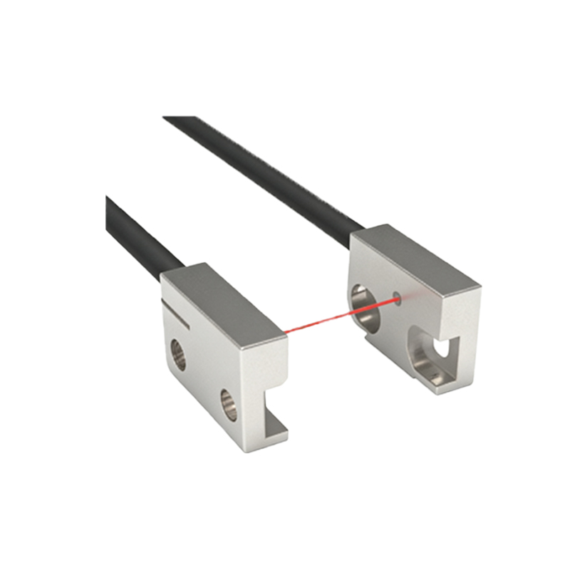
Optimizing the Detection Distance and Emitter Power
Response speed can be degraded by excessive detection distance or insufficient emitter power. When the distance between the sensor and target is too large, the received light intensity drops, increasing the time needed for signal processing. Engineers should adjust the sensing range to match the application, using sensors with adjustable gain or power output. For example, in a high-speed conveyor system, reducing the distance from 2 meters to 1 meter can cut response time by 30%, as the optical signal-to-noise ratio improves. Additionally, using high-power LEDs or laser emitters ensures stable signal strength, minimizing false triggers and improving response consistency.
Minimizing External Light Interference and Electrical Noise
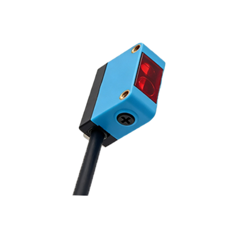
Ambient light from sources like incandescent bulbs, sunlight, or welding arcs can cause photoelectric sensors to delay response or produce errors. Implementing optical filters that match the emitter wavelength (e.g., 660nm red light or 940nm infrared) effectively blocks unwanted wavelengths. Shielded cables and proper grounding are essential to reduce electrical noise from motors or drives, which can corrupt the sensor's output signal. For critical applications, using sensors with built-in noise suppression algorithms or differential detection techniques enhances immunity. A simple test: if the sensor response varies with factory lighting changes, add a hood or install a polarized filter.
Selecting the Right Output Type and Circuit Load
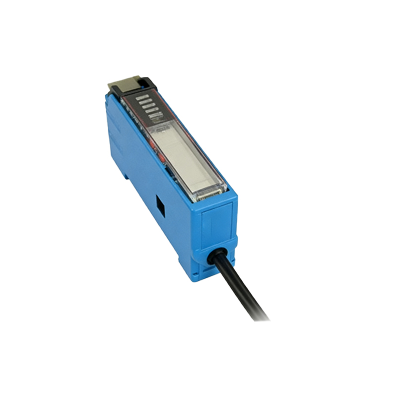
The sensor's output configuration (NPN, PNP, push-pull, or relay) and the connected load (PLC input, relay coil, or solenoid) significantly affect response time. Relay outputs are slow (10-20ms), while transistor outputs (NPN/PNP) can achieve 0.1-1ms response. For high-speed applications, use digital transistor outputs with low capacitive loads. Additionally, avoid long cable runs exceeding 10 meters without signal repeaters, as capacitance-induced delays can exceed 5ms. Matching the sensor output to the input characteristics of the controller (e.g., fast input modules with 0.5ms cycle time) ensures minimal latency.
Implementing Advanced Timing and Calibration Techniques
Many modern photoelectric sensors offer adjustable response time settings (e.g., 0.1ms, 1ms, or 10ms) via potentiometers or software. For fast-moving objects (e.g., bottles at 500 units per minute), set the response time to the minimum stable value. Calibration using a known target can fine-tune the threshold level, preventing false triggers from dust or vibration. Engineers should also consider using sensors with background suppression or fixed-focus optics, which eliminate the need for lengthy processing of reflected signals. Periodic maintenance (cleaning lenses, checking alignment) further sustains optimal response.