Introduction to Phase Difference in Photoelectric Sensors
In industrial automation, photoelectric sensors are critical for detecting objects, measuring distances, and ensuring precise control. One key parameter in advanced sensor applications is the phase difference, which arises when comparing signals from multiple sensor elements or modulated light sources. This phase difference is mathematically expressed by the formula: Δφ = (2πd)/λ, where Δφ is the phase difference in radians, d is the path difference between two light beams, and λ is the wavelength of the light source. Engineers rely on this relationship to enhance measurement accuracy in systems like laser scanners, optical encoders, and reflective sensors.
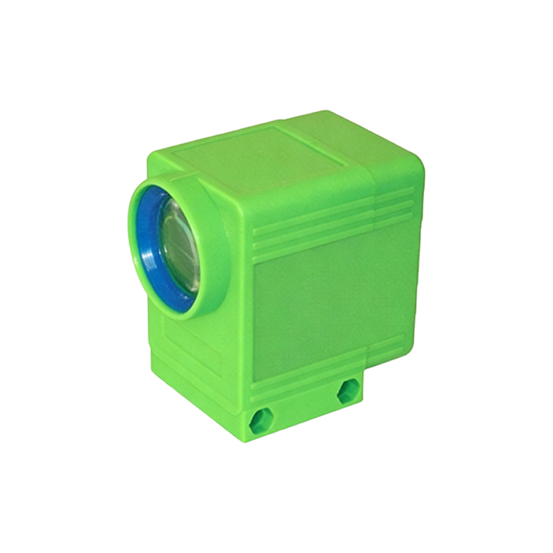
Derivation and Physical Meaning of the Formula
The phase difference formula originates from the wave nature of light. When two coherent light waves travel different distances before reaching a detector, their temporal alignment shifts, creating a measurable phase offset. For example, in a time-of-flight photoelectric sensor, the emitted modulated light reflects off a target and returns; the phase change between the emitted and received signals corresponds to the target distance. The formula Δφ = (2πd)/λ simplifies this: a path difference d equals a fraction of the wavelength λ, resulting in a proportional phase shift. This allows engineers to calculate distances with sub-millimeter precision, even in harsh industrial environments.
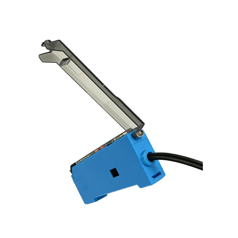
Practical Implementation in Sensor Design
In practice, photoelectric sensors often use modulated infrared or laser light to minimize ambient interference. The phase difference is measured by comparing the transmitted and received signals using phase-locked loops or digital signal processors. For instance, in a through-beam sensor, the emitter sends a continuous wave; the receiver detects the phase shift caused by an object interrupting the beam. By applying the formula, the system can determine object thickness or position. Designers must account for factors like signal attenuation, reflection angles, and electronic noise, which can introduce phase errors. Therefore, calibration routines are essential to maintain accuracy.
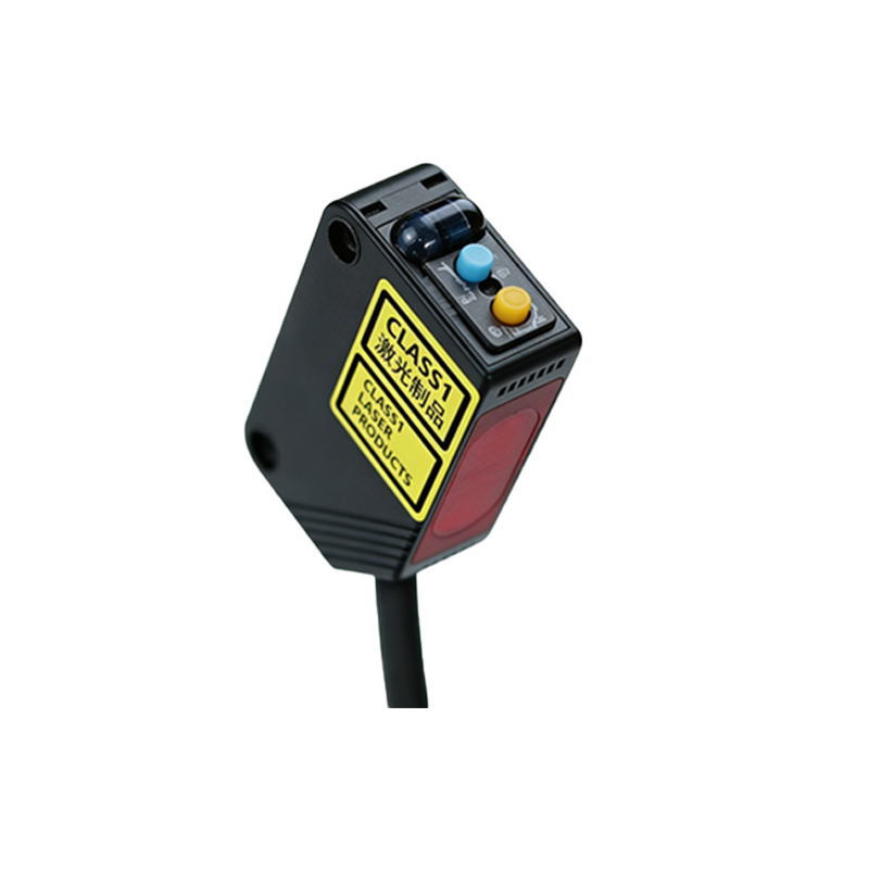
Advanced Applications and Error Mitigation
Beyond basic detection, phase-based photoelectric sensors are used in 3D scanning, robot guidance, and quality inspection. For example, in a triangulation sensor, multiple receivers capture phase differences from a scanned surface, enabling height mapping. The formula also supports differential measurements, where two channels compare phase shifts to cancel out common-mode disturbances like temperature drift. Engineers should consider that the formula assumes monochromatic light and ideal conditions; real-world deviations require compensation algorithms, such as averaging multiple readings or using reference signals.
Conclusion and Engineering Considerations
Mastering the phase difference formula equips engineers to optimize photoelectric sensor performance. Key takeaways include: the direct relationship between path difference and phase shift, the need for stable wavelength sources, and the importance of signal processing. When selecting sensors for industrial lines, check operating wavelength ranges and phase resolution specifications. Regular maintenance, such as cleaning optics and recalibrating, ensures consistent results. By integrating this formula into design and troubleshooting, professionals achieve higher reliability in automation systems.