2026-06-02
Tech Hub
By 创始人
Precision Speed Difference Measurement Using Photoelectric Sensors in Industrial Motor Systems
Introduction to Photoelectric Sensors for Speed Monitoring
Photoelectric sensors are widely utilized in industrial automation for non-contact speed measurement. These sensors operate by emitting a light beam and detecting interruptions or reflections caused by rotating targets, such as encoder discs or reflective tapes mounted on motor shafts. In applications requiring speed difference control—such as conveyor belt synchronization, multi-motor drives, or paper processing lines—photoelectric sensors offer high accuracy, fast response, and immunity to electrical noise. Their ability to measure both high and low rotational speeds makes them ideal for dynamic speed regulation tasks.
Operating Principle of Photoelectric Speed Difference Measurement
The core principle involves generating pulse signals proportional to the rotational speed. A photoelectric sensor, typically a through-beam or retro-reflective type, is aligned with a rotating disc featuring equally spaced slots or reflective marks. As the shaft rotates, the sensor outputs a square wave pulse train, where the frequency f = (N * RPM) / 60, with N being the number of slots. For speed difference measurement, two sensors are placed on two separate shafts. The pulse signals are fed into a programmable logic controller or a dedicated frequency comparator. The difference in pulse frequency directly corresponds to the speed difference, allowing real-time correction via variable frequency drives or servo controllers.
Selection Criteria for Photoelectric Sensors in Speed Difference Applications
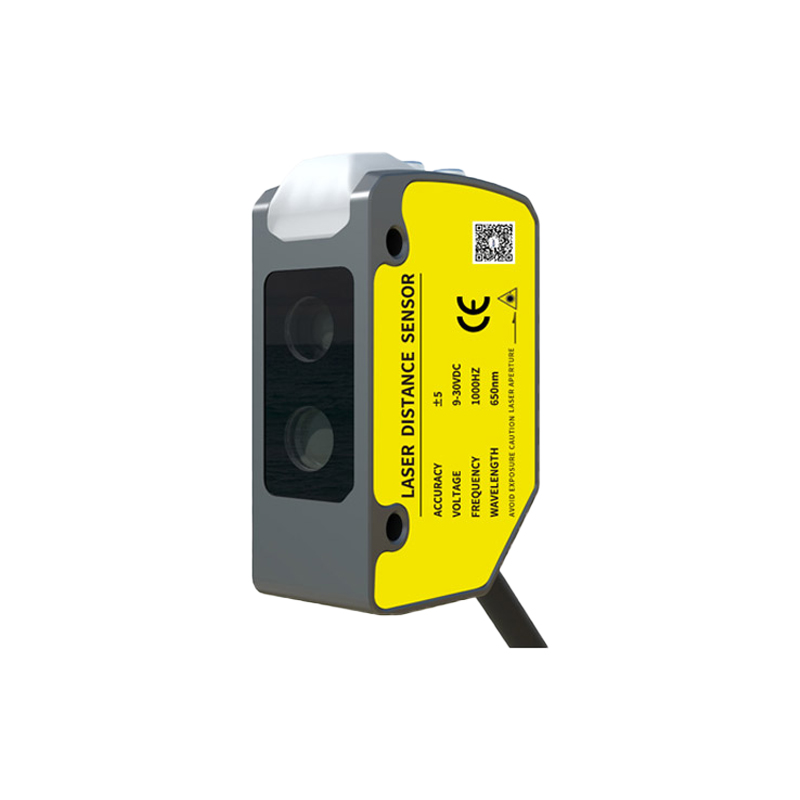
Choosing the right sensor is critical for reliable speed difference detection. Consider the following factors: 1) Sensing range: For shafts with large diameters or vibrations, a long-range retro-reflective sensor (e.g., up to 10 meters) is preferred. 2) Response time: For high-speed applications, sensors with response times below 1 ms (e.g., 0.5 ms) are necessary to avoid pulse loss. 3) Output type: NPN or PNP open-collector outputs are standard, but for long cable runs, push-pull or line driver outputs ensure signal integrity. 4) Environmental resistance: In dusty or oily environments, sensors with IP67 rating and metal housings are recommended. 5) Target material: For reflective tape, a polarized retro-reflective sensor eliminates false triggers from shiny surfaces.
Installation and Alignment for Optimal Accuracy
Proper installation ensures measurement consistency. Mount the sensor bracket rigidly to minimize vibration-induced errors. For through-beam sensors, align the emitter and receiver precisely within ±0.5 degrees to maintain a stable light path. For retro-reflective sensors, the reflective tape must be mounted perpendicular to the sensor beam. The rotating disc should have an even number of slots (e.g., 60) to generate a high-resolution pulse stream. Calibrate the sensor threshold to avoid false triggers from ambient light or dust. After installation, verify the output frequency with a tachometer under no-load and full-load conditions.
Signal Processing for Speed Difference Calculation
The raw pulse signals from two sensors require conditioning before comparison. Use a high-speed counter module in the PLC to measure each pulse train’s frequency. A common method is to count pulses over a fixed time window (e.g., 1 second) for both channels. The speed difference ΔS = (F1 - F2) * (60 / N), where F1 and F2 are frequencies in Hz. For real-time control, a PID algorithm adjusts the motor speed of the slower shaft to match the faster one. In cases of high noise, apply a digital low-pass filter (e.g., moving average) to smooth frequency readings without introducing phase lag.
Common Challenges and Troubleshooting Tips
Practical issues include: 1) Signal interference from variable frequency drives: Use shielded cables and ferrite beads on sensor lines. 2) Misaligned sensors due to thermal expansion: Implement a flexible coupling or use a sensor with a wide sensing beam. 3) Dust accumulation on optics: Install air purge systems or use sensors with auto-diagnostic functions. 4) Speed difference drift: Check for bearing wear or belt slippage. 5) Low pulse counts at slow speeds: Increase the number of slots on the encoder disc or use a high-resolution sensor. Regular calibration and preventive maintenance are essential for long-term reliability.
Conclusion: Enhancing System Efficiency with Photoelectric Speed Difference Control
Integrating photoelectric sensors for speed difference measurement significantly improves process control in industrial applications. By selecting appropriate sensors, ensuring precise installation, and employing robust signal processing, engineers can achieve synchronization errors below 0.01%. This reduces mechanical wear, minimizes product defects, and enhances overall system efficiency. As Industry 4.0 evolves, combining photoelectric sensors with IoT platforms enables predictive maintenance and adaptive speed control, driving higher productivity in manufacturing environments.