In the realm of industrial automation and machinery control, the accurate measurement of rotational speed is paramount for ensuring operational efficiency, safety, and predictive maintenance. Speed proximity sensors, often simply called speed sensors, are the unsung heroes in this domain. These devices detect the presence, absence, or proximity of a target, typically a gear tooth, keyway, or other rotating feature, and convert this detection into an electrical signal proportional to the rotational speed. Unlike physical contact tachometers, these sensors operate without touching the moving part, leading to reduced wear, higher reliability, and the ability to function in harsh environments.
The fundamental operating principle of most industrial speed proximity sensors is based on electromagnetic induction or eddy currents. A common type is the inductive proximity sensor. It contains an oscillator circuit that generates a high-frequency electromagnetic field at its active face. When a ferrous metal target, such as a gear tooth, enters this field, it causes eddy currents to form on the target's surface. This results in a dampening or loading of the oscillator's amplitude. This change is detected by a threshold circuit, which then switches the sensor's output state. By counting the pulses generated as each tooth passes the sensor over a given time period, the rotational speed (RPM) can be precisely calculated. For non-ferrous metals, specialized capacitive or ultrasonic sensors might be employed, though inductive types dominate for metallic targets.
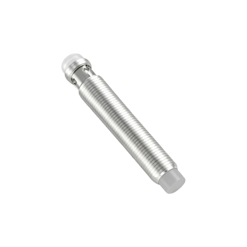
Another highly prevalent technology is the Hall-effect sensor. These sensors detect changes in a magnetic field. A permanent magnet is either integrated into the sensor or mounted on the rotating shaft. As a ferrous target passes, it disturbs the magnetic field, or a multi-pole magnetic ring rotates past the sensor. The Hall-effect element within the sensor produces a voltage proportional to the magnetic flux density, creating a clean digital or analog output signal. Hall-effect sensors are renowned for their ability to operate at very low speeds, even down to zero RPM, and are less sensitive to vibration and oil contamination compared to some inductive sensors.
The applications for speed proximity sensors are vast and critical. In the automotive industry, they are essential for anti-lock braking systems (ABS), measuring wheel speed to prevent lock-up. They monitor crankshaft and camshaft position and speed for precise engine timing and fuel injection. In industrial manufacturing, they are used on conveyor belts to control product flow, on motors and turbines for overspeed protection, and in packaging machinery to synchronize operations. Wind turbines rely on them to monitor blade and generator speed for optimal power output and safety shutdowns. They are also fundamental in railway systems for measuring axle speed, directly contributing to train control and safety systems.
Selecting the right speed proximity sensor requires careful consideration of several parameters. First, the target material and size must be compatible with the sensor's technology (e.g., inductive for ferrous metals). The sensing distance, or the gap required between the sensor and the target, is crucial for mechanical design. The required output signal type must be specified: a digital pulse (PNP/NPN), a sinusoidal wave, or an analog voltage/current proportional to speed. Environmental factors are often decisive. Sensors may need to withstand extreme temperatures, high levels of vibration, exposure to coolants, oils, or washdowns, requiring specific ingress protection (IP) ratings like IP67 or IP69K. Finally, the electrical requirements, such as supply voltage and current consumption, must match the control system's capabilities.
Installation and maintenance, while generally straightforward, demand attention to detail. Proper alignment between the sensor and the target is critical for generating a consistent signal. The air gap must be set according to the manufacturer's specifications—too large, and the signal weakens; too small, and risk of physical damage increases. Shielding cables is often necessary in electrically noisy environments to prevent signal interference. Routine checks should involve verifying the output signal with an oscilloscope or multimeter and ensuring the sensor face and target remain clean from debris, metallic dust, or buildup, which can attenuate the sensing field.
In conclusion, speed proximity sensors are indispensable components in modern engineering. Their non-contact operation provides a robust and reliable method for monitoring rotational speed across countless industries. From enabling advanced automotive safety features to ensuring the smooth and safe operation of massive industrial turbines, these devices translate physical motion into actionable data. Understanding their operating principles, types, and key selection criteria empowers engineers and technicians to implement effective speed monitoring solutions, thereby enhancing system performance, safety, and longevity. As machinery becomes more intelligent and interconnected, the role of precise, reliable speed sensing will only continue to grow in importance.