Introduction to Photoelectric Sensor Calibration
Photoelectric sensors are critical components in industrial automation, used for object detection, distance measurement, and quality control. However, their performance degrades over time due to dust, vibration, and component aging. Proper calibration ensures accuracy, reliability, and extended sensor lifespan. This guide covers standard calibration procedures for through-beam, retro-reflective, and diffuse sensors, including necessary tools, setup, and verification steps.
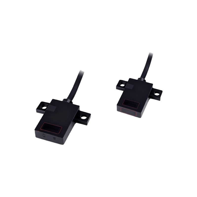
Understanding Sensor Types and Calibration Needs
Before calibration, identify the sensor type and its operating principle. Through-beam sensors require alignment of emitter and receiver. Retro-reflective sensors rely on a reflector, while diffuse sensors depend on target reflectivity. Each type has unique calibration parameters: sensitivity, switching threshold, and response time. Always refer to the manufacturer datasheet for specific voltage, current, and environmental tolerances.

Essential Tools and Safety Precautions
A typical calibration kit includes a light source simulator, an oscilloscope or multimeter, a test target with known reflectivity, and mounting fixtures. Ensure the system is de-energized before connecting test equipment. Use ESD-safe tools and wear antistatic wrist straps to prevent damage to sensitive electronics. Verify that the calibration environment is free from ambient light interference, as stray photons can skew readings.
Step-by-Step Calibration Procedure
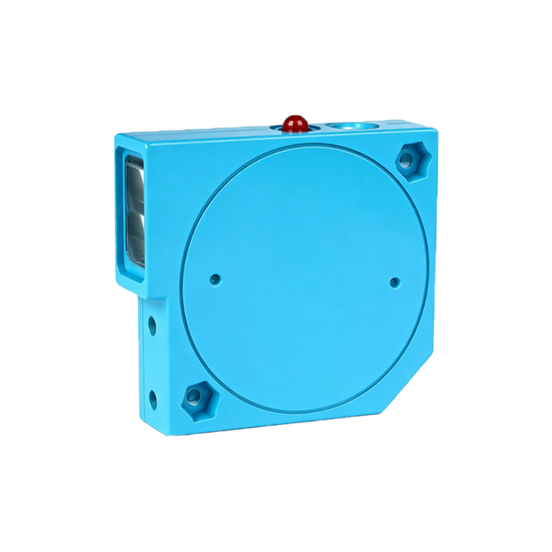
First, power the sensor and connect the output to an oscilloscope. Place the test target at the specified sensing distance. Adjust the sensitivity potentiometer (or use digital interface commands) until the output signal reaches the desired threshold voltage, typically 2.5V for PNP or 0.5V for NPN outputs. For retro-reflective sensors, align the reflector within the beam cone using a laser alignment tool. Perform a hysteresis test by moving the target in and out of range, confirming the ON/OFF switching differential is within +/-10% of the set point.
Verification and Documentation
After calibration, run a full cycle test: 100 consecutive detections at maximum speed. Record the response time and signal-to-noise ratio. Use a histogram to check for jitter or false triggers. Document the calibration date, technician ID, sensor serial number, and final parameters. This data supports ISO 9001 compliance and predictive maintenance scheduling.
Common Calibration Errors and Troubleshooting
Frequent issues include insufficient sensitivity due to dirty optics, incorrect target color, or misaligned emitter/receiver. If the sensor fails to trigger, check the supply voltage and load impedance. For diffuse sensors, adjust the background suppression setting if the target is glossy or transparent. Refer to the error code table in the user manual for advanced diagnosis.
Conclusion: Maintaining Calibration Integrity
Regular calibration intervals depend on operating conditions: harsh environments (dust, vibration) require monthly checks; clean rooms need quarterly verification. Use automated calibration stations for high-volume production lines. Always label calibrated sensors with a tamper-evident seal. By following these best practices, you reduce downtime, improve process yield, and ensure consistent product quality.