Introduction to Photoelectric Sensors
Photoelectric sensors are fundamental components in industrial automation and electronic systems. They operate by detecting the presence, absence, or distance of an object using a light transmitter and receiver. The core principle involves emitting a beam of light—often infrared, visible, or laser—and measuring changes in the received light intensity caused by an object interrupting or reflecting the beam. These sensors are prized for their non-contact operation, high speed, and reliability, making them ideal for applications like object counting, positioning, and safety systems. Understanding their basic functionality is the first step toward designing or implementing an effective sensor circuit.
Key Components in a Basic Circuit
A simple photoelectric sensor circuit typically consists of a few essential components. The light-emitting element, usually an infrared LED (Light Emitting Diode), serves as the transmitter. The receiver is commonly a phototransistor or photodiode, which converts incoming light into an electrical signal. Supporting components include current-limiting resistors for the LED to prevent burnout, a pull-up or load resistor for the phototransistor to set the output voltage level, and sometimes an operational amplifier (op-amp) to boost weak signals. A power supply, often ranging from 5V to 24V DC, provides the necessary energy. These parts form the backbone of most entry-level photoelectric sensor designs.
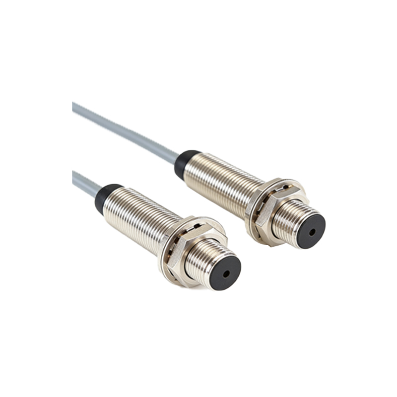
Step-by-Step Circuit Design
Designing a basic photoelectric sensor circuit involves several clear steps. First, select an infrared LED and a matching phototransistor with compatible wavelength specifications, typically around 940nm for common IR pairs. Connect the LED in series with a current-limiting resistor to the positive supply; a 220-ohm resistor is typical for a 5V supply to achieve about 20mA current. For the phototransistor, connect its collector to the positive supply via a pull-up resistor (e.g., 10k ohms) and its emitter to ground. The output signal is taken from the collector node. When light from the LED strikes the phototransistor, it conducts, pulling the output voltage low; when blocked, the output goes high. This creates a digital signal indicating object detection.
Wiring and Connection Diagram
A practical wiring diagram illustrates these connections clearly. Draw the IR LED anode to Vcc (e.g., +5V) through the 220-ohm resistor, with the cathode to ground. Place the phototransistor with its collector linked to Vcc via the 10k-ohm resistor and its emitter directly to ground. Label the output point between the collector and the pull-up resistor. For enhanced clarity, use standard schematic symbols: a diode symbol with arrows for the LED and a transistor symbol with light arrows for the phototransistor. Ensure all connections are neat, with power and ground lines distinctly marked. This visual guide helps beginners avoid common mistakes like reversed polarity or incorrect resistor placement.
Testing and Calibration Tips
After assembling the circuit, testing is crucial for reliable operation. Power the circuit and use a multimeter to measure the output voltage. With no obstruction, the phototransistor should be illuminated, yielding a low output (near 0V). When an object blocks the light path, the output should rise to near Vcc. If readings are unstable, adjust the resistor values: increase the LED resistor to dim the light if oversensitive, or decrease the pull-up resistor for a stronger signal. Ensure the LED and phototransistor are aligned properly, as misalignment can cause false triggers. Testing in ambient light conditions may require shielding to prevent interference from external light sources.
Common Applications and Variations
This simple circuit forms the basis for numerous real-world applications. In industrial settings, it can be used for object detection on conveyor belts, jam detection in printers, or limit switching in machinery. For hobbyists, it's ideal for DIY projects like automatic door sensors, line-following robots, or visitor counters. Variations include reflective sensors, where the LED and receiver are side-by-side to detect light bounced off an object, and through-beam sensors, with separate transmitter and receiver units for long-range detection. Adding an op-amp can create analog sensors for distance measurement, while integrating a microcontroller allows for programmable logic and advanced filtering.
Troubleshooting Frequent Issues
Beginners often encounter issues like no output signal, weak response, or erratic behavior. First, check all connections for loose wires or cold solder joints. Verify component orientations: LEDs and phototransistors are polarity-sensitive. Measure voltages across resistors to ensure correct current flow. Ambient light interference can be mitigated by using modulated IR light and a tuned receiver, or simply by enclosing the sensor in a dark tube. If the sensor reacts slowly, consider using a photodiode with faster response time instead of a phototransistor. Always consult datasheets for component specifications to match your circuit's requirements.
Conclusion and Further Learning
Mastering a simple photoelectric sensor circuit opens doors to more complex automation projects. This guide provides a solid foundation in component selection, design, and testing. To deepen your knowledge, explore datasheets for advanced sensors, study signal conditioning techniques, or experiment with different optical configurations. Online resources and electronics forums offer valuable community support. Remember, practice is key—start with this basic setup, then iterate by adding features like adjustable sensitivity or wireless output. With these skills, you can confidently tackle sensor-based challenges in both professional and personal projects.