Proximity sensor alarm circuits are fundamental components in modern security, automation, and industrial systems. These circuits detect the presence or absence of an object within a specified range without physical contact, triggering an audible, visual, or electronic alert. The core principle relies on the sensor's ability to sense a target through various means, such as electromagnetic fields, infrared light, or ultrasonic sound waves. The circuit's design integrates this sensing capability with a signal processing unit and an output alarm mechanism.
The most common types of proximity sensors used in alarm circuits are inductive, capacitive, and infrared (IR). Inductive sensors are ideal for detecting metallic objects. They generate an oscillating electromagnetic field. When a metal object enters this field, it induces eddy currents within the object, which dampens the oscillator's amplitude. This change is detected by the circuit, which then activates the alarm. These are extensively used in machine safety guards, metal detection, and automotive applications.
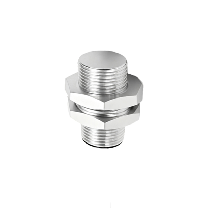
Capacitive sensors, on the other hand, can detect both metallic and non-metallic materials like liquids, wood, or plastics. They function by measuring changes in capacitance. The sensor forms one plate of a capacitor, with the target object acting as the other plate. As the object approaches, the capacitance increases. The circuit monitors this change and triggers the alarm once it crosses a predefined threshold. This makes them suitable for liquid level detection, material handling, and touch-sensitive interfaces.
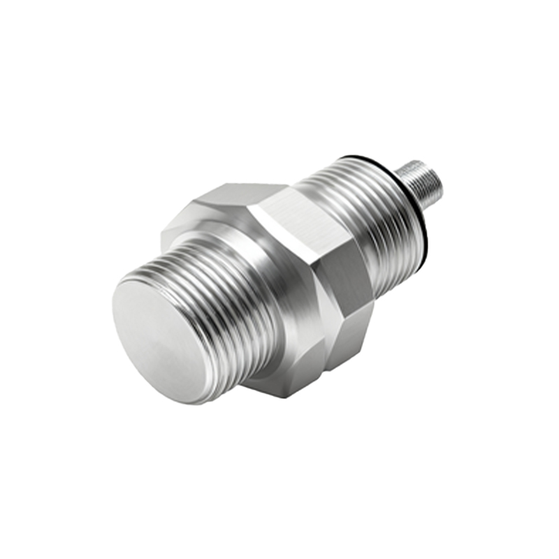
Infrared proximity sensors operate by emitting an IR beam and measuring the reflection. A photodiode or phototransistor receives the reflected light. The intensity of the received signal correlates with the distance to the object. When the reflected intensity surpasses a set level, indicating an object is too close, the alarm activates. Passive Infrared (PIR) sensors, which detect heat radiation from moving bodies, are a popular subset for security and lighting automation.
A basic alarm circuit consists of several key stages. First, the proximity sensor module acts as the input. Its output is typically a digital signal (HIGH/LOW) or an analog voltage that varies with distance. This signal is fed into a conditioning circuit, often involving an operational amplifier (op-amp) configured as a comparator. The comparator compares the sensor signal with a reference voltage set by a potentiometer, which defines the detection sensitivity or range. When the sensor signal exceeds the reference, the comparator's output state flips.
This flip in output state is the trigger for the alarm stage. For a simple audible alarm, this signal can drive a transistor that powers a buzzer or a piezoelectric speaker. For visual alerts, LEDs or flashing beacon lights can be used. In more advanced systems, the trigger signal is sent to a microcontroller (like an Arduino or ESP32). The microcontroller provides immense flexibility, allowing for programmable delay times, adjustable sensitivity via code, multiple alarm modes, and connectivity options like Wi-Fi or GSM to send remote alerts.
Design considerations are crucial for reliability. Power supply stability is paramount; voltage regulators ensure consistent sensor and circuit operation. False alarms can be mitigated by incorporating a timing circuit or software debounce to require the detected signal to be present for a minimum duration. Environmental factors are also critical. Inductive sensors can be affected by nearby metals, capacitive sensors by humidity, and IR sensors by ambient light. Proper shielding, filtering, and sensor selection for the specific environment are necessary.
Implementing a proximity alarm circuit begins with selecting the appropriate sensor for the target material and required range. Next, design the signal conditioning and comparison circuitry on a breadboard for testing. Calibrate the sensitivity potentiometer to achieve the desired detection zone. Finally, integrate the alarm output device. For permanent installations, transferring the design to a printed circuit board (PCB) enhances durability.
Applications are vast. In home security, these circuits form the basis of door/window intrusion alarms. In industrial settings, they ensure machine operator safety by halting equipment when a hand is detected in a danger zone. In automotive systems, they provide parking assistance. In public facilities, they enable touchless faucets and hand dryers. The simplicity, reliability, and non-contact nature of proximity sensor alarm circuits ensure their continued and expanding role in an automated world.
Troubleshooting common issues often involves checking power connections, verifying sensor alignment and range, adjusting the sensitivity control, and testing the alarm output component independently. With a systematic approach, a robust and effective proximity-based alarm system can be successfully deployed for countless protective and automated functions.