Understanding Infrared Photoelectric Sensors
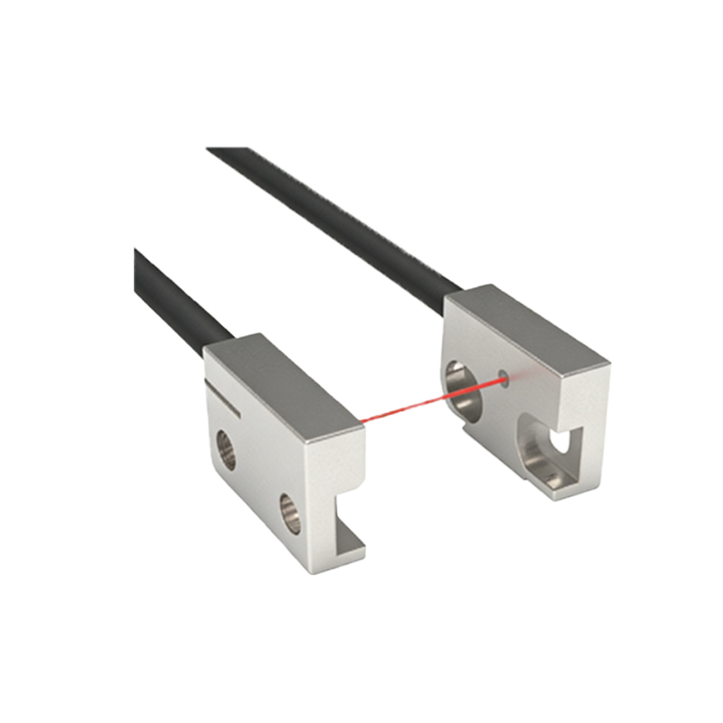
Infrared photoelectric sensors are fundamental components in automation and detection systems. They operate by emitting an infrared light beam and detecting its reflection or interruption. There are two primary types: reflective (or diffuse) sensors, where the emitter and receiver are housed together and detect objects that reflect the IR beam back, and through-beam (or opposed) sensors, which consist of separate emitter and receiver units, detecting objects that break the beam. These sensors provide a simple digital or analog output signal indicating the presence or absence of an object. For digital types, the output is typically a high or low logic level, making them straightforward to interface with microcontrollers like the STM32. Understanding the sensor's datasheet is crucial, particularly its operating voltage, output type (NPN/PNP for digital, voltage range for analog), and response time.
Hardware Connection and Circuit Design
Connecting an infrared sensor to an STM32 requires careful attention to voltage levels and signal types. First, ensure the sensor's power supply matches its requirements, often 5V or 3.3V. Many STM32 boards, such as the Nucleo series, provide both. For a digital output sensor, connect its output pin to any STM32 GPIO pin configured as a digital input. If the sensor operates at 5V and the STM32 GPIO is 3.3V tolerant, a simple resistor divider or a level-shifter circuit might be necessary to protect the microcontroller. For sensors with an NPN open-collector output, a pull-up resistor (e.g., 10kΩ) to 3.3V is required on the GPIO line. Always connect the ground (GND) pins of the sensor and the STM32 together to establish a common reference. For analog output sensors, connect the output to an STM32 analog-to-digital converter (ADC) input pin. Proper decoupling capacitors near the sensor's power pins are recommended for stable operation.
Configuring STM32 GPIO and Peripheral Settings
Using STM32CubeIDE or similar tools simplifies peripheral configuration. For a digital sensor, configure the connected GPIO pin as Input mode. You can choose between floating input, pull-up, or pull-down depending on your circuit; if an external pull-up resistor is used, select floating input. Enable the GPIO clock in the initialization code. For reading the pin's state, use the HAL_GPIO_ReadPin() function in a polling method, or configure an external interrupt (EXTI) for immediate response to state changes. This is highly efficient for event-driven detection. For analog sensors, configure the corresponding ADC channel. Set the ADC resolution (e.g., 12-bit), sampling time, and enable continuous or single conversion mode. Using DMA for ADC conversion is advantageous for continuous sampling without CPU intervention, allowing for filtering or averaging of the sensor data in the background.
Implementing the Sensor Reading Logic
The software logic depends on the application. For basic digital object detection, a simple loop reading the GPIO pin suffices. However, to avoid noise, implement a simple debouncing algorithm in software, such as reading the pin state multiple times over a short period before confirming a change. When using EXTI interrupts, the detection callback function should be kept minimal, perhaps just setting a flag for the main loop to process. For analog sensors, the read ADC value must be correlated to a physical property, like distance or reflectance. This often requires calibration. You might map the ADC value to a known range using linear interpolation. For more robust sensing, especially in variable ambient light conditions, consider modulating the IR emitter (if controllable) and synchronizing the receiver reading to filter out constant ambient IR noise, though many integrated sensors handle this internally.
Practical Code Example and Troubleshooting
Here is a concise example for a digital sensor on PA0 using EXTI, and an analog sensor on PA1 using ADC polling. First, the GPIO and ADC are configured via CubeMX. The digital interrupt handler sets a flag. The main loop checks this flag and toggles an LED. For the analog sensor, a value is read and potentially converted to distance.
``c
// Digital Sensor using EXTI
void HAL_GPIO_EXTI_Callback(uint16_t GPIO_Pin) {
if (GPIO_Pin == GPIO_PIN_0) {
object_detected_flag = 1;
}
}
// In main loop
if(object_detected_flag){
HAL_GPIO_TogglePin(LED_GPIO_Port, LED_Pin);
object_detected_flag = 0;
}
// Analog Sensor using ADC Polling
HAL_ADC_Start(&hadc1);
if (HAL_ADC_PollForConversion(&hadc1, 10) == HAL_OK) {
adc_value = HAL_ADC_GetValue(&hadc1);
// Convert adc_value to distance (requires calibration)
}
HAL_ADC_Stop(&hadc1);
``
Common issues include no signal or erratic readings. Verify connections with a multimeter. Ensure the sensor's IR LED is emitting light (visible as a faint red glow with some cameras). Check for electrical noise by adding a small capacitor (e.g., 100nF) across the sensor's output and ground. For analog sensors, ensure the ADC reference voltage is stable. Always consult the specific STM32 reference manual for detailed register configurations if not using HAL libraries.