Understanding the Basic Components
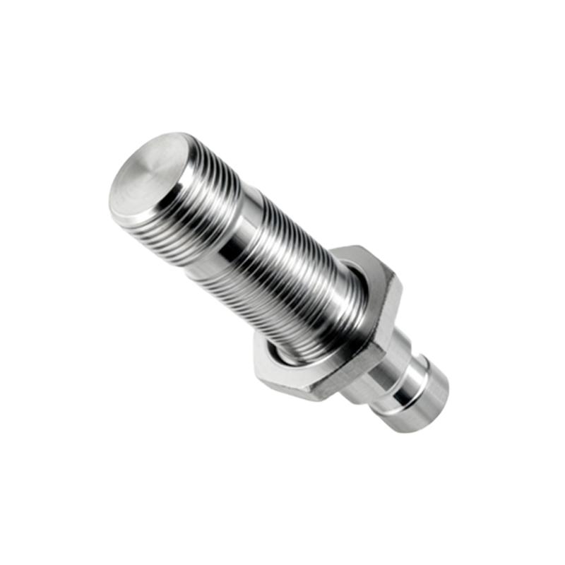
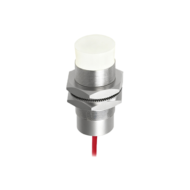
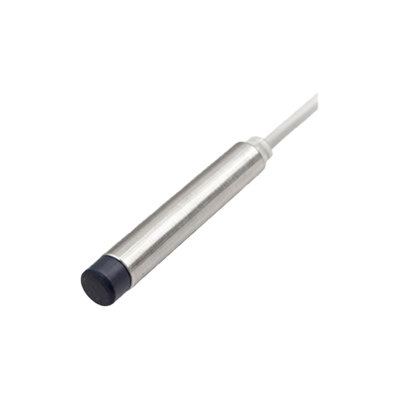
In industrial automation and control systems, the reliable operation of machinery often hinges on the precise interaction between sensing devices and power control elements. Two fundamental components in this relationship are proximity sensors and contactors. A proximity sensor is a non-contact device that detects the presence or absence of an object within its sensing field, typically outputting a digital signal. A contactor is an electrically controlled switch used for switching a power circuit, similar to a relay but designed to handle higher current loads, often for controlling motors, heaters, or lighting banks. The core principle of connecting them involves using the sensor's output signal to control the coil of the contactor, thereby enabling or disabling the high-power load based on the sensed condition.
Selecting Compatible Devices
Before making any connections, ensuring compatibility between the sensor and contactor is paramount. First, verify the sensor's output type. Common types include PNP (sourcing) and NPN (sinking) DC outputs, as well as AC two-wire versions. The contactor coil's voltage and current rating must match the sensor's output capability. For instance, a 24V DC PNP sensor should control a contactor with a 24V DC coil. Exceeding the sensor's maximum switching current can damage its output transistor. Secondly, consider the electrical characteristics: the inrush current of the contactor coil during energization can be significantly higher than its holding current. The sensor must be rated to handle this surge. Always consult the datasheets of both devices to confirm electrical compatibility.
Standard Wiring Configurations
The wiring diagram varies based on the sensor type and the desired control logic. For a standard 3-wire DC proximity sensor (PNP), the typical connection is as follows: Connect the brown wire (typically +V) to the positive DC supply. Connect the blue wire (typically 0V) to the negative DC supply. The black wire is the signal output. To control a contactor, connect this black wire to one terminal of the contactor's coil. Connect the other terminal of the coil back to the negative DC supply (for PNP). When the sensor detects an object, it switches its output, connecting the coil to positive voltage, energizing the contactor and closing its main power contacts. For an NPN sensor, the logic is inverted; the output sinks current to negative. Safety note: Always implement proper fusing for the control circuit.
Incorporating Interlocks and Safety
In practical applications, direct sensor-to-contactor wiring is often insufficient. Safety and operational logic require additional components. A critical practice is to wire the sensor through a safety relay or a programmable logic controller (PLC) to integrate emergency stop circuits, door interlocks, or other safety functions. Furthermore, for motor control, overload protection relays are always connected in series with the contactor coil. The sensor's output would typically energize a control relay or a PLC input, whose output then drives the contactor coil through the overload relay's normally closed contact. This layered approach isolates the low-current sensor circuit from potential faults in the power circuit and ensures compliance with safety standards like IEC 60204-1.
Addressing Noise and Interference
Industrial environments are electrically noisy, which can cause false triggering of sensors or contactors. To ensure reliable operation, employ noise suppression techniques. For AC coil contactors, use an RC snubber circuit (a resistor and capacitor in series) across the coil terminals to suppress voltage spikes generated when the coil is de-energized. For DC circuits, a freewheeling diode (also known as a flyback diode) must be installed across the contactor coil, with the cathode to positive, to protect the sensor's solid-state output from inductive kickback. Always use shielded cables for sensor connections, grounding the shield at one end only (usually the control panel end), and keep control wiring separate from high-power cables.
Testing and Troubleshooting Procedures
After installation, systematic testing is essential. First, perform a continuity and insulation resistance test on all wiring with power disconnected. Apply power to the control circuit only. Use a multimeter to verify the sensor's output voltage changes state when an object is presented. Observe if the contactor coil energizes audibly and if its auxiliary contacts change state as expected. If the contactor does not pull in, check for voltage across the coil. If it's present, the coil may be faulty. If absent, trace back through the circuit: check the sensor output, any intermediate relays, fuses, and the overload relay's contact. A common issue is misidentifying PNP versus NPN wiring. Remember,