Introduction to Photoelectric Speed Sensing
Photoelectric sensors have become a cornerstone technology for non-contact speed measurement in modern industrial automation and machinery. These devices operate on the fundamental principle of converting light signals into electrical signals to detect the presence, absence, or motion of an object. For rotational speed measurement, they offer distinct advantages over mechanical tachometers and magnetic sensors, including higher accuracy, minimal wear and tear, and the ability to function without physical contact with the rotating component. This makes them ideal for applications ranging from high-speed conveyor systems and motor control to precision manufacturing and automotive testing. The core mechanism involves interrupting a light beam, typically from an LED or laser source, with a rotating element. The frequency of these interruptions is directly proportional to the rotational speed, providing a clean, digital signal for processing by a Programmable Logic Controller (PLC) or data acquisition system.
Core Operating Principles and Configurations
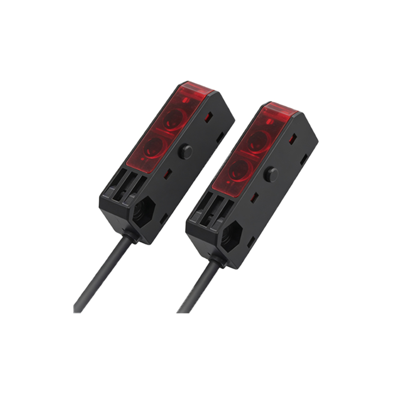
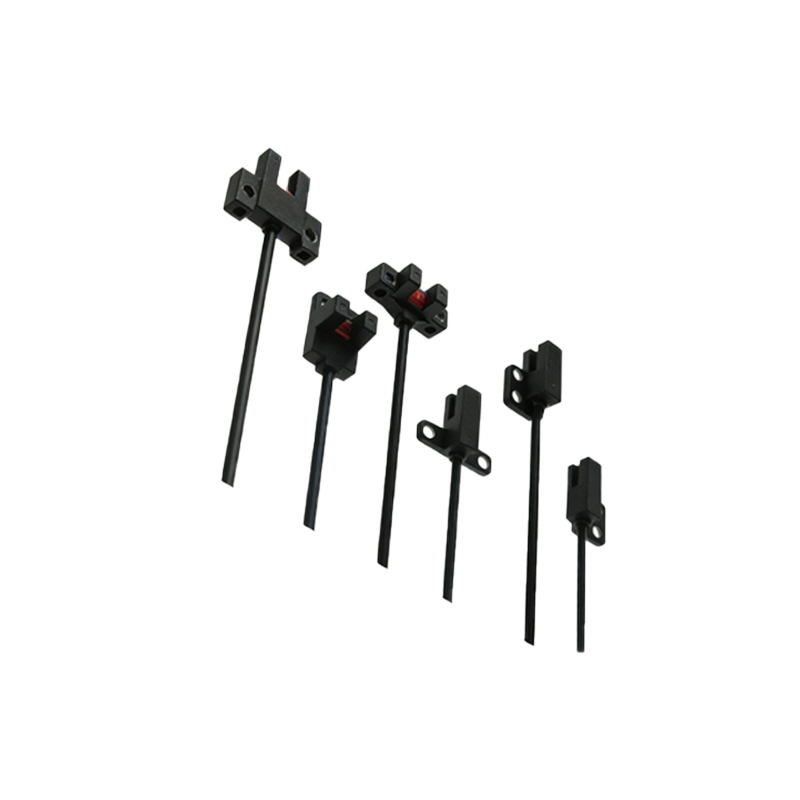
The two primary configurations for photoelectric speed sensing are the through-beam (or opposed) mode and the reflective (or proximity) mode. In the through-beam setup, the emitter and receiver are positioned opposite each other. A rotating disk, often with slots or reflective marks, is placed in the beam path. As the disk rotates, it alternately blocks and allows the light to pass, generating a pulse train at the receiver. The reflective mode utilizes a single housing containing both the emitter and receiver. It detects light reflected from a pre-marked or specially prepared surface on the rotating shaft or wheel. A common implementation involves attaching a single piece of reflective tape to a shaft. Each revolution causes one strong reflective pulse, which is counted over a precise time interval to calculate RPM (Revolutions Per Minute). The choice between these configurations depends on factors like installation space, required accuracy, and environmental conditions.
Key Components and Sensor Selection Criteria
Selecting the appropriate photoelectric sensor for a specific speed measurement task requires careful consideration of several technical parameters. The light source is critical; infrared LEDs are common for their immunity to ambient light, while laser diodes provide highly focused beams for detecting very small or fast-moving targets. The sensor's response time, measured in microseconds, determines the maximum rotational speed it can accurately measure. For instance, a sensor with a 50 µs response time can theoretically handle frequencies up to 10 kHz. The sensing distance and required resolution (pulses per revolution) are also vital. High-resolution measurements often use an encoder disk with multiple slots. Environmental robustness is non-negotiable in industrial settings; sensors must have suitable Ingress Protection (IP) ratings against dust and moisture and be resistant to vibration, temperature fluctuations, and potential exposure to oils or coolants.
Signal Processing and RPM Calculation Methodology
The raw output from a photoelectric sensor is an analog or digital pulse signal. This signal requires conditioning and processing to yield a useful speed reading. Typically, the signal is converted into a clean, square-wave digital pulse using a comparator circuit to eliminate noise. The fundamental calculation for rotational speed is straightforward: RPM = (Number of Pulses Counted / Pulses per Revolution) * (60 / Measurement Time in Seconds). For example, if a sensor configured for 1 pulse per revolution counts 120 pulses in 2 seconds, the RPM is (120/1) * (60/2) = 3600 RPM. For higher precision, especially at variable speeds, advanced methods like frequency-to-voltage conversion or direct period measurement (timing the interval between consecutive pulses) are employed. These processed signals are then fed into control systems for real-time monitoring, closed-loop control, or data logging.
Common Industrial Applications and Use Cases
The versatility of photoelectric speed sensors ensures their widespread adoption across diverse sectors. In the automotive industry, they are used on engine test stands to measure crankshaft speed and on assembly lines to monitor wheel rotation for balancing. Within packaging machinery, they synchronize the speed of film feeders and product conveyors. On printing presses, they ensure precise registration by monitoring roller speed. In the textile industry, they control the speed of spindles and looms. A critical application is in variable frequency drive (VFD) systems for motor control, where speed feedback is essential for maintaining setpoints and efficiency. Their non-contact nature also makes them perfect for measuring the speed of delicate or hazardous materials where physical contact is impossible or undesirable.
Installation Best Practices and Troubleshooting Tips
Proper installation is paramount for reliable operation. Key considerations include precise alignment of through-beam components, ensuring the reflective target provides adequate contrast, and minimizing the effects of ambient light interference, which may require using a modulated light source. The sensor should be mounted securely to avoid vibration-induced errors. Cable routing should be away from high-power cables to prevent electromagnetic interference. Common issues include erratic readings or loss of signal. Troubleshooting should start with verifying alignment and checking for obstructions in the beam path. Inspect the target surface for dirt or damage that could affect reflectivity. Verify the power supply and check cable connections for integrity. Using an oscilloscope to observe the raw sensor output pulse waveform is often the most effective diagnostic step to distinguish between mechanical issues and electronic signal problems.
Advantages, Limitations, and Comparison with Other Technologies
Photoelectric sensors excel in providing high-accuracy, non-contact speed measurement with excellent resolution and fast response. They are generally immune to magnetic fields, a significant advantage over inductive proximity sensors. However, they have limitations. Their performance can be degraded by environmental contaminants like dust, fog, or heavy grease that obscure the light path. Certain materials or colors may not reflect light adequately for reflective sensors. Compared to magnetic encoders or Hall-effect sensors, photoelectric types can be more sensitive to harsh environments but offer superior resolution. Compared to direct mechanical coupling, they eliminate backlash and wear. The choice often boils down to a trade-off between the required precision, environmental challenges, and cost. For clean, high-speed, and high-accuracy applications, photoelectric sensors are frequently the optimal solution.
Future Trends and Technological Advancements
The future of photoelectric speed sensing is aligned with broader trends in Industry 4.0 and smart manufacturing. Sensors are increasingly becoming "intelligent," with embedded microprocessors that perform onboard calculation of RPM, diagnostics, and even predictive maintenance alerts by analyzing signal trends. The integration of IO-Link and other digital communication protocols allows for seamless parameter setting, remote monitoring, and integration into Industrial Internet of Things (IIoT) networks. Advancements in laser and lens technology are enabling measurements at greater distances and on smaller targets. Furthermore, the development of robust housings and coatings is expanding their usability in extreme environments previously dominated by other sensor types. As machinery demands higher speeds and tighter tolerances, the role of precise, reliable photoelectric speed measurement will only become more critical.