Understanding Photoelectric Sensor Fundamentals
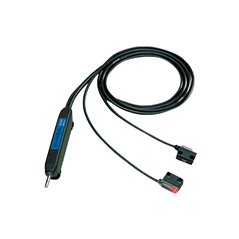
A photoelectric sensor is a device that uses light to detect the presence, absence, or distance of an object. Its core components typically include an emitter (light source), a receiver (photodetector), and supporting electronics. The emitter projects a beam of light, which is then either received directly, reflected off a target, or reflected by a dedicated reflector. The receiver converts the received light intensity into an electrical signal, which is processed by the internal circuitry to produce a discrete output signal (e.g., ON/OFF). Common types include through-beam, retro-reflective, and diffuse reflective sensors, each with distinct operating principles and applications. Understanding this basic operation is the first step in effective troubleshooting. A malfunction can occur in any of these core sections: the light source may degrade, the receiver may become contaminated or damaged, or the electronic circuitry may fail.
Visual Inspection and Physical Examination
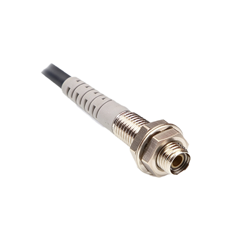
Begin any diagnostic procedure with a thorough visual and physical inspection. Check the sensor housing for any signs of physical damage, such as cracks, dents, or severe scratches that could compromise its environmental sealing (IP rating). Inspect the lens of both the emitter and receiver for dirt, dust, oil film, condensation, or scratches. Even a thin layer of contamination can significantly attenuate the light beam, leading to unreliable operation. Ensure that the sensor is securely mounted and that there is no excessive vibration, which could loosen connections or damage internal components. Verify the alignment for through-beam and retro-reflective types; even a slight misalignment can cause failure. Examine the cable and connector for wear, cuts, or pin damage. A simple cleaning of the lenses with a soft, lint-free cloth and an appropriate cleaner can often resolve performance issues.
Power Supply and Wiring Verification
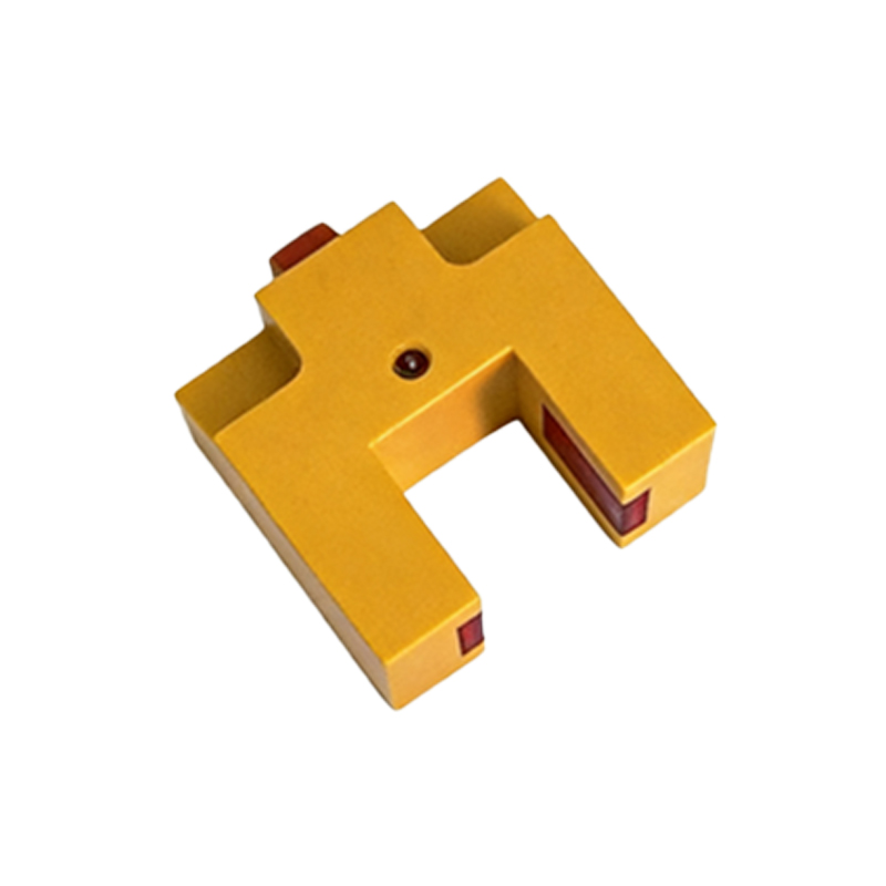
An incorrect or unstable power supply is a frequent cause of sensor malfunction. Using a digital multimeter, verify that the voltage at the sensor's terminals matches its specified operating range (e.g., 10-30 VDC). Check for voltage drops under load, which might indicate insufficient wire gauge or a poor connection. Ensure proper polarity for DC sensors. Inspect all wiring connections for tightness and corrosion. For sensors with cable outlets, gently wiggle the cable near the gland while monitoring the output to check for intermittent breaks. Follow the manufacturer's wiring diagram precisely, confirming the connections for power, output, and, if applicable, the diagnostic or teaching wire. A sensor will not function correctly without clean, stable power and proper electrical connections.
Testing Operational Response
The most direct test involves observing the sensor's response to a target. For a through-beam sensor, interrupt the beam between the separate emitter and receiver units. For a retro-reflective sensor, break the beam to the reflector. For a diffuse sensor, move a standard target into and out of the sensing range. Observe the sensor's status indicator LED (most sensors have a built-in LED that indicates power and output state). The LED should change state (e.g., from green to orange, or from on to off) reliably with each target action. Simultaneously, use your multimeter set to measure DC voltage to check the output signal at the switching output wire. Confirm it changes from a high to low state (or vice-versa, depending on the logic) corresponding to the LED and the target's presence. An inconsistent or absent change indicates a problem.
Assessing Sensing Range and Beam Strength
Performance degradation often manifests as a reduced effective sensing range. If possible, test the sensor at its specified maximum sensing distance using a standard target as defined by the manufacturer (often a white Kodak card or a specified material and size). Gradually move the target towards the sensor until it detects it. Compare this distance to the sensor's datasheet specification. Many modern sensors have a teach-in function or a signal strength indicator (often via a sequence of LED blinks or a dedicated monitor output). This feature provides invaluable insight into the received light intensity. A consistently low signal strength, even with a clean lens and proper alignment, suggests aging of the LED emitter, degradation of the receiver, or other internal component failure.
Analyzing Environmental Interference
The operating environment can severely impact photoelectric sensor performance. Ambient light from sunlight, welding arcs, or high-intensity lamps can saturate the receiver, causing false triggers or failure to detect. Check for sources of optical interference. Acoustic noise or electrical noise from motors, variable frequency drives (VFDs), or solenoids can induce false signals in the sensor's circuitry. Ensure proper shielding, grounding, and physical separation from noise sources. For sensors operating in environments with temperature extremes, verify that the current ambient temperature is within the sensor's rated operating range. Condensation forming on the lens due to rapid temperature cycling is a common issue. Consider environmental factors as a potential root cause when other basic checks seem satisfactory.
Utilizing Advanced Diagnostics and Substitution
When basic tests are inconclusive, employ more advanced methods. An oscilloscope can be used to examine the quality of the power supply line for noise and to observe the sensor's output switching characteristics for abnormalities. Some programmable sensors offer detailed diagnostic data via IO-Link or other digital communication protocols, providing parameters like internal temperature, operating hours, and signal strength history. The most definitive field test, however, is often substitution. Replace the suspect sensor with a known-good unit of the same model, ensuring identical wiring and configuration. If the new sensor operates flawlessly, the original sensor is confirmed faulty. This method isolates the problem to the sensor unit itself, ruling out all external factors.
Interpreting Failure Modes and Final Determination
Specific symptoms can point to likely failure modes. A sensor with no power indicator LED is likely suffering from a power supply issue, broken internal fuse, or catastrophic circuit failure. A solid power LED but no response to target interruption often indicates a failed emitter or receiver. An erratic, chattering output typically suggests marginal signal strength due to contamination, misalignment, or interference. A sensor that operates only at very short distances points to a weakened emitter. If, after systematic inspection, cleaning, alignment, power verification, environmental control, and signal strength assessment, the sensor still fails to perform reliably within its published specifications, it must be determined as bad or faulty. For critical applications, proactive replacement based on performance trends (like declining signal strength) is recommended over waiting for complete failure.