Introduction to Photoelectric Sensor Architecture
A photoelectric sensor, a cornerstone of industrial automation, operates on a deceptively simple principle: it uses light to detect the presence, absence, or distance of an object. The reliability and precision of these sensors, however, hinge on the seamless integration of their internal components. Understanding each part's name and function is crucial for engineers during selection, integration, troubleshooting, and maintenance. This article provides a detailed breakdown of the fundamental components that constitute a typical photoelectric sensor, presented in a clear, industry-standard terminology.
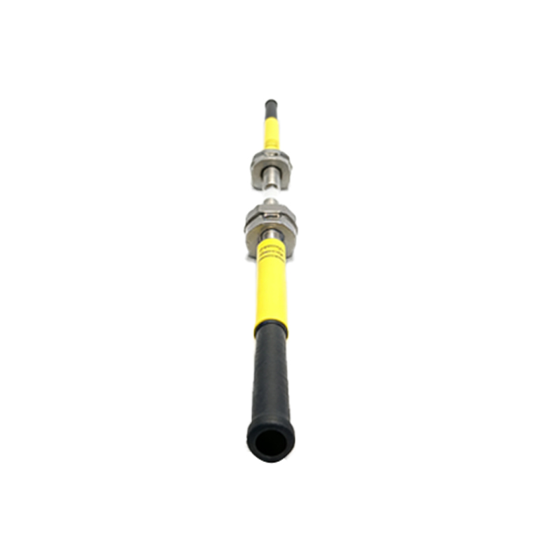
Light Emitter: The Source of the Signal
At the heart of the transmitting side is the Light Emitting Element. This component generates the modulated light beam that serves as the sensor's probing signal. The most common types are Light Emitting Diodes (LEDs), prized for their long life, low heat generation, and fast response times. For standard applications, visible red or infrared LEDs are prevalent. For demanding tasks requiring high precision or resistance to ambient light interference, Laser Diodes are employed, producing a concentrated, coherent beam. The emitter is housed within a Lens that collimates or focuses the emitted light into a precise beam, defining the sensor's sensing range and spot size.
Light Receiver: Capturing the Signal
The counterpart to the emitter is the Photodetector or Light Receiving Element. This component's sole purpose is to convert incoming light photons back into an electrical signal. The predominant technology used is the Phototransistor or Photodiode. These semiconductors exhibit a change in current proportional to the intensity of the light striking them. The receiver also features a Lens to collect and direct the light (whether reflected or direct) onto the sensitive area of the photodetector efficiently. The performance of the receiver directly impacts the sensor's sensitivity and immunity to noise.
Control Circuitry: The Brain of the Operation
The raw signals from the emitter and receiver are managed by the sensor's internal Control Circuit or Amplifier. This printed circuit board (PCB) is the computational core. It typically contains the Oscillator Circuit that drives and modulates the LED at a specific high frequency, a critical feature that allows the sensor to distinguish its own light from ambient background light. The circuit also includes an Amplifier that boosts the weak signal from the photodetector. Following amplification, a Demodulator filters out signals not matching the emitter's modulation frequency. Finally, a Comparator evaluates the processed signal against a preset threshold to make the definitive detection decision and control the output state.
Housing and Connectors: The Physical Interface
All internal components are protected by the Sensor Housing or Body. This enclosure, typically made from metal (like nickel-plated brass or stainless steel) or robust engineering plastics (such as PBT or PVDF), provides mechanical strength, environmental sealing (often rated IP67 or IP69K), and protection against electromagnetic interference (EMI). The Electrical Connection point is equally vital. This may be a fixed Cable with strain relief or a quick-disconnect Connector (e.g., M8 or M12 types standard in automation). This interface delivers power (usually 10-30V DC) and carries the switched Output Signal, which can be from a transistor (NPN/PNP) or a relay.
Indicator and Adjustment Mechanisms
For setup and diagnostics, most sensors incorporate Status Indicators. These are typically LEDs that show power status (Power LED), a stable light when operational, and a Stability/Function LED that may blink or change color to indicate signal strength, alignment, or an output state. Many sensors also include a means for sensitivity adjustment. This can be a physical Potentiometer accessed via a screwdriver or, in more advanced models, a Teach-In Button for one-touch programming of the sensing threshold, simplifying setup dramatically.
Auxiliary Components for Specific Modes
Depending on the sensing mode—through-beam, retro-reflective, or diffuse—additional specific components come into play. A Through-Beam sensor set consists of separate emitter and receiver units. A Retro-Reflective sensor includes a Polarizing Filter in front of its receiver lens. This filter ensures the sensor only recognizes light reflected from a specialized Corner Cube Retroreflector, rejecting false signals from shiny objects. In Diffuse or proximity sensors with background suppression, a key internal component is the Position Sensitive Device (PSD), which allows the sensor to determine the angle of the returning light and thus reject reflections from surfaces beyond a set distance.