Introduction to Slot-Type Photoelectric Sensors
A slot-type photoelectric sensor, often referred to as a through-beam sensor, is a fundamental component in industrial automation. Its core function is to detect the presence or absence of an object by utilizing a light emitter and a receiver housed in a single U-shaped body. The object to be detected passes through the "slot" or gap, interrupting the light beam. This design creates a self-contained, opposed-mode sensing system, which is highly reliable for detecting small, opaque objects. Engineers favor this configuration for its ease of installation and alignment, as the emitter and receiver are pre-aligned in a fixed housing, eliminating the need for separate mounting and tedious optical alignment procedures common with separate emitter-receiver pairs. The robustness of this design makes it suitable for challenging environments found in manufacturing, packaging, and material handling.
Deciphering the Schematic Diagram
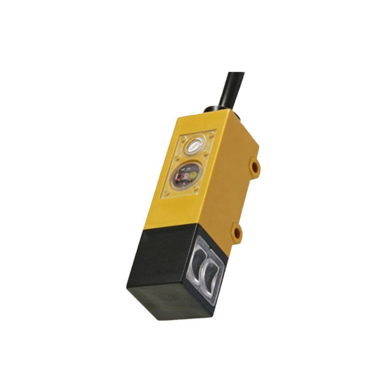
The schematic diagram of a slot-type photoelectric sensor is key to understanding its electrical integration. Typically, the diagram will illustrate the sensor's internal circuitry, including the light-emitting diode (LED), the phototransistor or photodiode receiver, and the output switching element. Common output types include NPN (sinking) and PNP (sourcing) transistor outputs. The diagram clearly labels the connection terminals: usually, brown wire for positive DC supply (V+), blue wire for negative/common (0V), and black wire for the switched output signal. Some models include additional wires for output configuration like light-on/dark-on mode. A crucial symbol on the diagram is the LED indicator, showing the status of the beam and output. Understanding this schematic is essential for proper wiring to a programmable logic controller (PLC) or other control systems, ensuring correct logic for object detection.
Key Components and Their Functions
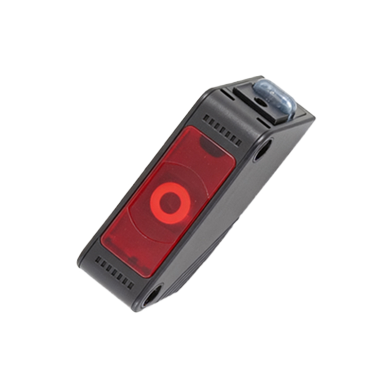
Examining the diagram reveals several critical components. The infrared or visible red LED serves as the light source, chosen for its longevity and stability. Opposite the emitter is the photodetector, which converts the received light intensity into an electrical current. The heart of the sensor is the amplifier/comparator circuit, which processes the detector's signal. It compares the signal level to a predefined threshold to determine if the beam is interrupted (object present) or clear (object absent). This circuit then drives the output transistor. The housing itself is a key mechanical component, defining the slot width and depth, which determines the maximum size of object that can be detected and the sensing distance. Diagrams often note the housing material, such as ABS plastic or metal, indicating environmental resistance.
Understanding Timing Charts and Waveforms
Advanced datasheets include timing diagrams or waveform charts. These charts are vital for applications involving high-speed detection or specific response sequences. A typical timing chart plots the relationship between the object interrupting the beam (the input event) and the electrical response of the output transistor. It defines parameters like response time (the delay between beam interruption and output switch), reset time, and minimum detectable object width at a given speed. For sensors with a modulation feature (pulsed light), the diagram explains the carrier frequency, which makes the sensor immune to ambient light interference. Interpreting these charts allows engineers to select a sensor with a fast enough response time for their line speed and to correctly program PLC timers for reliable operation.
Application-Specific Diagram Variations
Diagrams can vary based on specific sensor features. For instance, a diagram for a "light-on" (LO) sensor will show the output active when the receiver gets light, while a "dark-on" (DO) sensor shows output active when the beam is blocked. Some sensors have a teach-in function or adjustable sensitivity, indicated by potentiometer symbols or digital interface lines on the diagram. Fork sensors, a subtype with a very narrow slot for detecting extremely small parts like electronic components, have diagrams emphasizing precision and high-speed response. Conversely, heavy-duty slot sensors for large object detection might highlight power supply specifications and overload protection circuits. Always cross-reference the diagram with the model's datasheet for application-specific details like temperature ratings, protection circuits (short-circuit, reverse polarity), and output configurations (NO/NC).
Installation and Alignment Considerations
While the slot-type design simplifies alignment, the installation diagram provides crucial guidelines. It specifies the mounting dimensions, slot orientation, and required clearances. A key point illustrated is ensuring that the object passes through the center of the slot for reliable beam interruption. The diagram also warns against mounting the sensor where accumulation of dust, dirt, or moisture could coat the optical windows, potentially causing false triggers. For environments with strong ambient light, the diagram might recommend using a shield or orienting the slot away from direct light sources. Proper mounting as per the mechanical diagram ensures optimal performance and longevity, preventing mechanical stress on the housing and maintaining the integrity of the sealed optical path.
Troubleshooting Using the Diagram
The sensor diagram is an indispensable tool for troubleshooting. If a sensor fails, the first step is to check the power supply connections against the wiring diagram. Using a multimeter, an engineer can verify voltage at the terminals. The status indicator LED, shown on the diagram, provides immediate visual feedback: a steady light may indicate beam received, a blinking light might mean beam blocked, and no light could signify power or sensor failure. By understanding the signal flow from the emitter to the output transistor, a technician can systematically isolate the fault—whether it's a damaged emitter, a faulty receiver, a compromised output stage, or an issue with the load (e.g., the PLC input). The diagram guides this logical diagnostic process.
Conclusion and Selection Criteria
In summary, the slot-type photoelectric sensor diagram is more than just a wiring guide; it is a comprehensive blueprint of the device's electrical, optical, and functional characteristics. Mastery of this diagram enables correct selection, integration, and maintenance. When selecting a sensor, engineers must correlate the diagram's specifications—such as slot dimensions, supply voltage, output type, response time, and connection scheme—with their application requirements. Choosing the correct model based on a thorough understanding of its documented diagram ensures reliable object detection, minimizes downtime, and contributes to efficient and robust automated system design. Always consult the manufacturer's latest datasheet for the most accurate and detailed diagrammatic information.