Understanding Proximity Switch Fundamentals
Proximity switches, or proximity sensors, are non-contact electronic devices designed to detect the presence or absence of an object within their sensing field. Unlike mechanical limit switches, they operate without physical contact, leading to higher reliability, longer lifespan, and faster response times in industrial environments. The core principle involves generating an electromagnetic field or a beam of light. When a target object enters this field, it causes a change in the sensor's oscillation or light reception, triggering a solid-state output switch. These sensors are categorized primarily by their sensing technology: inductive (for metallic objects), capacitive (for both metallic and non-metallic materials), and ultrasonic or photoelectric. Understanding this fundamental operation is crucial before examining the wiring schematics, as the type of sensor dictates specific wiring considerations, especially regarding output configurations (NPN vs. PNP) and power supply requirements.
Core Components and Terminal Identification
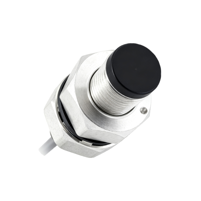
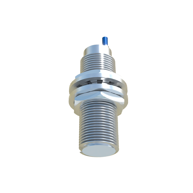
A standard three-wire DC proximity sensor is the most common configuration in industrial control panels. The terminals are typically marked, though the labeling can vary by manufacturer and region. The universal terminals are: Brown wire (or L+): This is the positive DC supply voltage line. For most sensors, this is connected to a 10-30V DC power source. Blue wire (or L- or N): This is the negative DC supply voltage line, or the 0V common return. It is connected to the DC power supply's negative terminal. Black wire (or OUT): This is the switched output signal line. The state of this output (on or off) changes based on the detection of the target. Some sensors may have a white wire for a second complementary output or other functions like timing. It is imperative to always consult the specific sensor's datasheet for accurate terminal identification, as wire colors are not universally standardized. The sensor housing also usually features a diagram or embossed markings near the conduit entry.
Wiring Diagram for NPN Sinking Output Sensors
An NPN output sensor acts as a sinking switch. In this configuration, the black output wire is connected to the load (e.g., a PLC input, relay coil, or indicator lamp). The other side of the load is connected to the positive supply voltage (+V). When the sensor detects an object, it switches on, allowing current to flow from the load, into the black output wire, through the sensor's internal NPN transistor, and out through the blue wire to the power supply negative. This "sinks" the current to ground. In a typical wiring diagram: The brown wire connects to +V DC (e.g., +24V). The blue wire connects to 0V DC (common). The black wire connects to one side of the load. The other side of the load is connected to +V DC. This configuration is often described as "positive switching" because the load is connected to the positive rail, and the sensor switches the negative side.
Wiring Diagram for PNP Sourcing Output Sensors
A PNP output sensor acts as a sourcing switch. Here, the black output wire is connected to the load. The other side of the load is connected to the negative supply voltage (0V). When activated, the sensor switches on, allowing current to flow from the brown wire (through the internal PNP transistor), out of the black output wire, through the load, and to the 0V terminal. This "sources" the current to the load. In the wiring diagram: The brown wire connects to +V DC. The blue wire connects to 0V DC. The black wire connects to one side of the load. The other side of the load is connected to 0V DC. This is commonly called "negative switching" because the load is connected to the common negative, and the sensor switches the positive side. The choice between NPN and PNP is critical and depends on the control system's input card design (sinking or sourcing).
Connecting to a Programmable Logic Controller (PLC)
Integrating a proximity sensor with a PLC is a fundamental task. First, identify whether the PLC's digital input module is designed for sinking (common positive) or sourcing (common negative) inputs. For a sinking input PLC module (where the common terminal is +24V), you must use a PNP (sourcing) proximity sensor. The sensor's black wire connects to the PLC input point, and the blue wire connects to the PLC's 0V terminal. For a sourcing input PLC module (common terminal is 0V), you must use an NPN (sinking) sensor. The sensor's black wire connects to the PLC input, and the brown