Introduction to Photoelectric Sensor Proximity Switches
In the realm of industrial automation, photoelectric sensor proximity switches stand as a cornerstone technology for non-contact object detection. Unlike mechanical limit switches or inductive/capacitive proximity sensors, these devices utilize light beams to detect the presence, absence, or distance of an object. Their fundamental principle involves an emitter, which projects a beam of light—often infrared, visible red, or laser—and a receiver that detects changes in this light beam. When an object interrupts or reflects the beam, the sensor's output state changes, triggering a control action. This method allows for detection over longer ranges and with a versatility that is unmatched by other proximity sensing technologies, making them indispensable in packaging, material handling, assembly, and safety applications.
Core Operating Principles and Sensing Modes
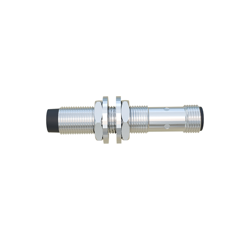
The functionality of photoelectric sensors is defined by their specific sensing mode, each suited for different environmental and application challenges. The three primary modes are through-beam, retro-reflective, and diffuse. Through-beam sensors, also known as opposed mode, consist of separate emitter and receiver units placed opposite each other. Detection occurs when an object breaks the beam. This mode offers the longest sensing range and highest reliability, as it is largely immune to object color, texture, or reflectivity. Retro-reflective sensors house both emitter and receiver in a single housing, using a reflector to bounce the light beam back. An object is detected when it interrupts this return path. These sensors require only one wiring point and offer good range, but they can be fooled by shiny objects that reflect light directly. Diffuse or proximity mode sensors also have a combined emitter and receiver, but they detect light reflected directly off the target object itself. While compact and easy to install, their effective range is shorter and performance is highly dependent on the object's color and surface properties.
Key Technical Specifications and Selection Criteria
Selecting the correct photoelectric sensor requires a careful analysis of several technical parameters. Sensing range is paramount; it defines the maximum distance at which the sensor can reliably detect a standard target. Light source type is another critical factor: modulated LED (infrared or visible) is common for general purpose use, offering long life and resistance to ambient light, while laser diodes provide extremely precise, small-spot detection for high-accuracy positioning. Response time, measured in milliseconds or microseconds, determines how fast the sensor can react to a changing target, which is crucial for high-speed production lines. The output configuration, typically NPN/PNP transistor or relay, must be compatible with the programmable logic controller (PLC) or other control system. Environmental factors such as temperature extremes, humidity, dust, oil, and vibration resistance (often indicated by an IP rating) are non-negotiable for ensuring long-term reliability in harsh industrial settings.
Advanced Features and Modern Innovations
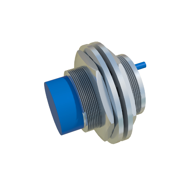
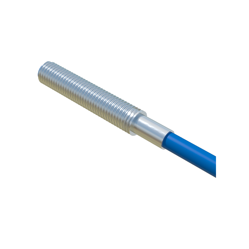
Modern photoelectric sensors incorporate sophisticated features that solve complex application problems. Background suppression is a technology, often using triangulation principles, that allows a diffuse sensor to ignore objects beyond a set distance, preventing false triggers from machinery or walls in the background. Fiber optic versions utilize flexible light guides to deliver and receive light, enabling sensing in extremely hot, cold, or space-constrained environments where the sensor electronics cannot be placed. Color sensors and contrast sensors are specialized variants that detect specific wavelengths or differences in reflectivity, used extensively in quality control. Furthermore, the integration of IO-Link communication protocol is a significant innovation, enabling sensors to transmit detailed diagnostic data (like lens contamination warnings or signal strength) and receive parameter changes digitally, paving the way for Industry 4.0 predictive maintenance and flexible production setups.
Common Application Challenges and Troubleshooting
Despite their robustness, photoelectric sensors can face operational challenges. Ambient light interference from sunlight or high-intensity factory lighting can swamp the sensor's receiver. Choosing a sensor with a modulated light source and proper optical filters is the primary defense. Lens contamination from dust, oil, or debris is a frequent cause of failure, leading to reduced sensing range or complete loss of function. Regular cleaning schedules or selecting sensors with built-in contamination alarms can mitigate this. Incorrect alignment, especially for through-beam and retro-reflective types, will cause unreliable operation. Using alignment tools or sensors with visible red light beams can simplify setup. Electrical noise from motors or variable frequency drives can also affect performance, necessitating proper shielding, grounding, and the use of sensors with robust electrical noise immunity ratings.
Installation Best Practices and Maintenance Guidelines
Proper installation is key to optimal sensor performance and longevity. Always secure the sensor firmly to minimize vibration, which can cause misalignment. For through-beam sensors, ensure precise alignment during installation and consider using mounting brackets for stability.