Introduction to Proximity Sensors in Hourglass Detection
Proximity sensors are fundamental components in modern industrial automation, particularly within systems designed for hourglass detection and timing mechanisms. These non-contact sensors detect the presence or absence of an object—in this context, the flow of sand granules—and provide critical feedback to control units. Their reliability is paramount for ensuring precise measurement and operational continuity. However, like all electronic components, they are susceptible to various anomalies that can compromise system integrity. This article delves into the common types of proximity sensors used, typical failure modes, and systematic troubleshooting approaches for engineers in the field.
Common Types of Proximity Sensors and Their Operating Principles
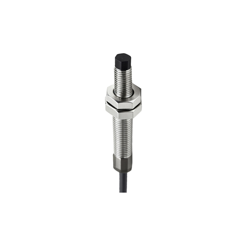
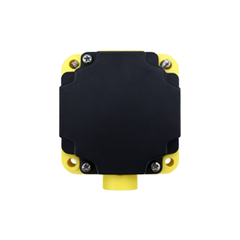
In hourglass detection applications, inductive and capacitive proximity sensors are most prevalent. Inductive sensors generate an electromagnetic field to detect metallic targets, such as a metal flap or indicator triggered by sand flow. Capacitive sensors, on the other hand, can detect both metallic and non-metallic materials, making them suitable for directly sensing the sand stream or a non-metal actuator. Understanding the specific operating principle of the installed sensor is the first step in effective diagnostics. Key parameters include sensing distance, response time, and output type (e.g., PNP/NPN, analog, or digital).
Identifying Typical Symptoms of Sensor Anomalies
Sensor malfunctions manifest in several observable symptoms within the hourglass system. Erratic triggering is a primary indicator, where the sensor provides intermittent signals despite a consistent sand flow. This may appear as skipped counts or irregular timing intervals. Complete failure to detect, resulting in a total loss of signal, is another critical symptom. Conversely, a sensor may exhibit constant activation, sending a continuous "on" signal even when no sand is present. Unstable output signals, often measured with an oscilloscope, and physical damage to the sensor housing or cable are also clear signs of underlying issues.
Root Causes of Proximity Sensor Failures
Multiple factors can lead to sensor anomalies. Environmental contamination is a major culprit; dust, moisture, or sand accumulation on the sensor face can attenuate or block the sensing field, especially problematic in granular material handling. Electrical interference from nearby high-voltage cables, motors, or variable frequency drives (VFDs) can induce noise into the sensor's signal lines, causing false triggers. Mechanical misalignment, where the sensor and its target are not properly aligned, reduces effective sensing range. Internal component degradation, such as oscillator circuit failure or output transistor breakdown, occurs over time due to thermal stress or voltage spikes. Finally, improper installation, including incorrect wiring, insufficient power supply voltage, or exceeding the sensor's environmental specifications (temperature, humidity), can precipitate early failure.
Systematic Troubleshooting and Diagnostic Procedures
A methodical approach is essential for efficient troubleshooting. Begin with a visual inspection of the sensor, its mounting, the target, and the cable for any obvious damage, debris, or misalignment. Clean the sensor face meticulously using appropriate methods. Next, verify electrical parameters using a multimeter: check the supply voltage at the sensor terminals to ensure it is within the specified range (typically 10-30V DC). Measure the output signal under different conditions (target present/absent). For sensors with diagnostic LEDs, observe their status. If possible, substitute the suspect sensor with a known-good unit of the same model to isolate the fault. Utilize an oscilloscope to analyze the output waveform for noise or instability, which can pinpoint interference issues.
Preventive Maintenance and Best Practices
Preventing sensor anomalies is more cost-effective than reactive repairs. Implement a regular maintenance schedule that includes cleaning sensor faces and checking for physical integrity. Ensure proper shielding and grounding of sensor cables, separating them from power lines to minimize electromagnetic interference. Use sensors with appropriate ingress protection (IP) ratings (e.g., IP67) for dusty or humid environments. During installation, strictly adhere to the manufacturer's guidelines regarding sensing distance, mounting, and electrical connections. Consider installing surge protection devices on the power supply line to guard against voltage transients. Periodically monitor system logs for any early signs of inconsistent sensor behavior.
Conclusion and Key Takeaways
Proximity sensor reliability is critical for the accuracy of hourglass detection systems. Anomalies typically stem from environmental, electrical, mechanical, or internal factors. A structured diagnostic process—encompassing visual inspection, electrical testing, and substitution—enables rapid fault isolation. Ultimately, a robust preventive maintenance regimen, coupled with correct sensor selection and installation, significantly enhances system uptime and measurement precision. Engineers must combine theoretical knowledge of sensor operation with practical diagnostic skills to maintain optimal system performance.