Proximity and photoelectric sensors are indispensable components in modern industrial automation, enabling non-contact detection of objects, precise positioning, and reliable process control. Proper adjustment is critical to ensure their accuracy, reliability, and longevity. This guide provides a systematic approach to adjusting these sensors, covering key principles, practical steps, and troubleshooting tips.
Understanding Sensor Types and Operating Principles
Before adjustment, identify the sensor type. Inductive proximity sensors detect metallic objects using an electromagnetic field. Capacitive sensors can detect both metallic and non-metallic materials by sensing changes in capacitance. Photoelectric sensors use a light beam (visible, infrared, or laser) and are categorized into through-beam, retro-reflective, and diffuse reflective types. Each type has a unique operating principle that dictates its adjustment methodology.

Pre-Adjustment Preparation
1. Safety First: Always lock out and tag out (LOTO) the associated machinery to prevent accidental startup.
2. Review Documentation: Consult the sensor's datasheet for its specifications: sensing distance, operating voltage, output type (PNP/NPN, NO/NC), and any special features like teach-in or IO-Link capability.
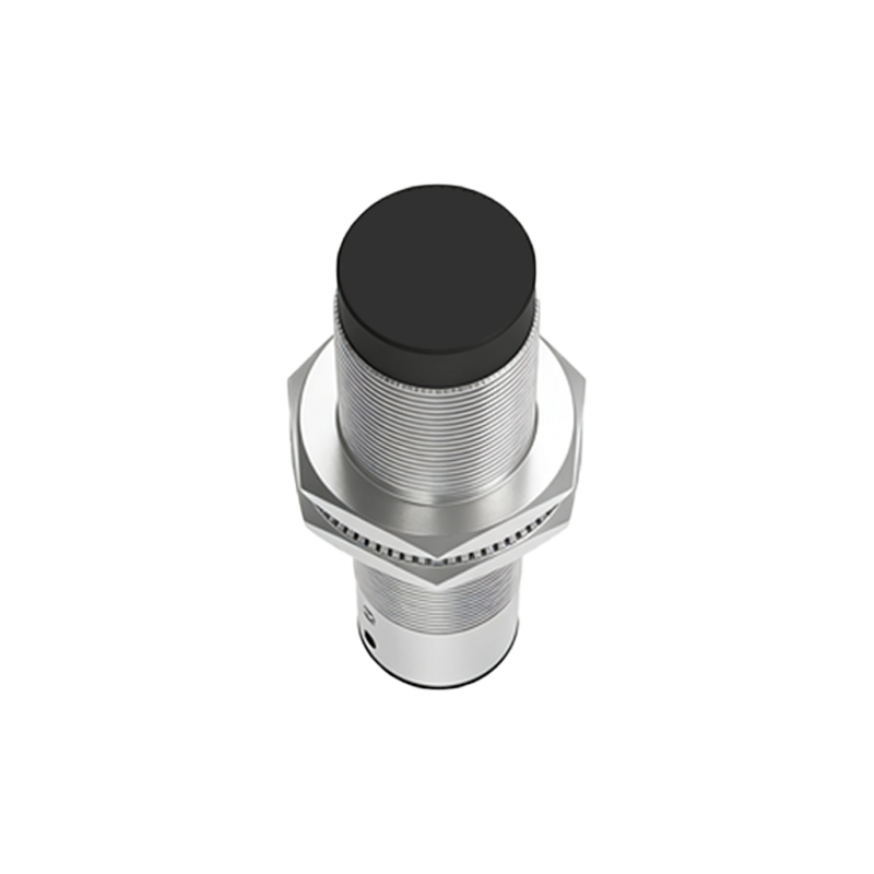
3. Visual Inspection: Check the sensor and its lens or sensing face for dirt, dust, oil, or physical damage. Clean carefully with a soft, lint-free cloth and appropriate cleaner. Ensure the mounting is secure and properly aligned.
4. Environmental Factors: Account for ambient conditions. Strong ambient light can affect photoelectric sensors. Electrical noise from motors or welders may interfere with sensor signals. Temperature extremes can impact performance.
Step-by-Step Adjustment Procedure
1. Electrical Connection and Power-Up:
Connect the sensor to the correct power supply as per the datasheet (typically 10-30V DC for standard models). Verify polarity. For 3-wire sensors, connect the brown wire (L+), blue wire (L-), and the black (or white) output wire to your controller. A stable power supply is essential.
2. Preliminary Alignment (For Photoelectric Sensors):
Through-Beam: Align the emitter and receiver visually. Many models have alignment LEDs. Rough alignment is often sufficient due to their generous beam angle.
Retro-Reflective: Point the sensor at the center of the reflector. Ensure the reflector is clean and undamaged.
Diffuse Reflective: Point the sensor at the target object's expected position.
3. Setting the Sensing Distance and Sensitivity:
This is the core of adjustment. Most sensors have a potentiometer or a push-button for setting the sensitivity/threshold.
Using a Potentiometer: Introduce the standard target (specified in the datasheet) at the required sensing distance. Slowly turn the potentiometer clockwise until the sensor's output LED switches state (e.g., from OFF to ON). Then, turn it slightly further (typically 1/4 to 1/2 turn) to provide a safety margin or "hysteresis." This margin prevents chattering or false triggers due to minor target variations or environmental drift.
Using Teach-In Function: For advanced sensors, press and hold the teach button (or follow a specific sequence) when the target is present at the desired detection point. The sensor automatically learns and sets the threshold. A second teach-in without the target may set the background suppression level.
4. Verifying the Sensing Window:
Do not just test with the target in one perfect position. Verify the entire "sensing window." Move the target towards and away from the sensor to confirm the actual operating range. For photoelectric sensors, check for potential false triggers from background objects or reflective surfaces by moving non-target objects through the detection field.
5. Output Verification and Timing:
Connect the sensor output to a PLC input or a pilot lamp. Verify the output switches reliably with each detection. For high-speed applications, check the sensor's response time and ensure it meets the cycle time requirements. Adjust the sensor's timing functions (on-delay, off-delay) if available and necessary for the application.
6. Final Securing and Documentation:
Once optimal settings are achieved, if the potentiometer has a lock screw, gently tighten it to prevent vibration from changing the setting. For photoelectric sensors, secure all mounting bolts. Document the settings, especially if the sensor has a digital interface.
Troubleshooting Common Issues
Sensor Not Detecting: Verify power, wiring, and output load. Check for incorrect sensor type (e.g., inductive sensor for a plastic part). Ensure the target is within the rated sensing distance and meets size/material requirements.
Inconsistent/Unstable Detection: This is often due to insufficient sensitivity margin. Re-adjust with a