Proximity switches are essential components in industrial automation, providing non-contact detection of metallic or non-metallic objects. Proper wiring of proximity switch sensors and their connectors is critical for ensuring reliable operation, safety, and longevity of machinery. This guide outlines step-by-step procedures, best practices, and common pitfalls to avoid when connecting these devices.
First, identify the type of proximity switch you are working with. Common types include inductive (for metallic objects), capacitive (for both metallic and non-metallic materials), and ultrasonic sensors. Each type may have specific wiring requirements, so refer to the manufacturer’s datasheet for voltage ratings, output configurations (e.g., NPN or PNP, normally open or closed), and connection diagrams. Typically, proximity switches have three or four wires: brown for positive voltage (10-30V DC), blue for negative or ground, black for output signal, and sometimes white for a second output or diagnostic function.
Begin by ensuring power is disconnected to prevent electrical hazards. Strip the insulation from the sensor wires and the corresponding power supply cables, exposing about 6-8mm of conductor. Use crimp terminals or solderless connectors for secure connections, avoiding loose strands that could cause short circuits. For the sensor head, match the wires to the connector pins as per the diagram—commonly, the brown wire connects to the positive terminal, blue to negative, and black to the output terminal. If using a pre-wired connector, insert the wires into the designated slots and tighten the screws firmly.
Shielding is crucial in environments with electromagnetic interference (EMI). Use shielded cables and ground the shield at one end only, typically at the controller side, to prevent ground loops. Route cables away from high-voltage lines and motors to minimize noise. For long cable runs, consider voltage drop; using thicker gauge wires can mitigate this issue. After wiring, perform a continuity test with a multimeter to check for correct connections and insulation integrity.
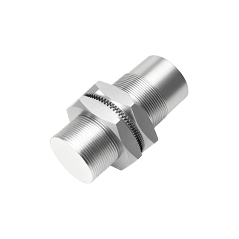
Common mistakes include reversing polarity, which can damage the sensor, or misconfiguring NPN vs. PNP outputs. NPN sensors sink current to ground, while PNP sources current from positive; ensure your PLC or controller matches the sensor type. Also, avoid over-tightening connector screws, as this may break wires. Once connected, power the system and test with a target object to verify detection range and output response. Regular maintenance, such as checking for corrosion or loose connections, helps prevent downtime.
In summary, wiring proximity switches correctly involves understanding sensor specifications, following color codes, using proper tools, and testing thoroughly. Adhering to these practices enhances system reliability and safety in industrial applications.
