Proximity sensors are widely used in industrial automation for detecting the presence or absence of objects without physical contact. Proper wiring is crucial to ensure reliable operation and prevent damage to the sensor or connected equipment. This guide provides a step-by-step approach to wiring proximity sensors, covering common types and practical considerations.
Most proximity sensors have three wires: brown (positive), blue (negative), and black (output). The brown wire connects to the positive terminal of the power supply, typically ranging from 10-30V DC for DC sensors. The blue wire connects to the negative terminal or ground. The black wire is the output signal, which switches based on object detection. For AC sensors, wiring may involve live (brown) and neutral (blue) connections, with the black wire as the output.
Before wiring, always refer to the sensor’s datasheet for voltage ratings, current limits, and wiring diagrams. Disconnect power to avoid electrical hazards. Use appropriate tools, such as wire strippers and screwdrivers, and ensure connections are tight to prevent loose contacts. Shielded cables are recommended in environments with electrical noise to reduce interference.
For two-wire sensors, wiring is simpler: one wire connects to power, and the other to the load. However, these sensors have a residual current when off, which may affect low-power circuits. Three-wire sensors offer better performance with separate power and output lines. Four-wire sensors include two outputs (e.g., normally open and normally closed) for flexible control.
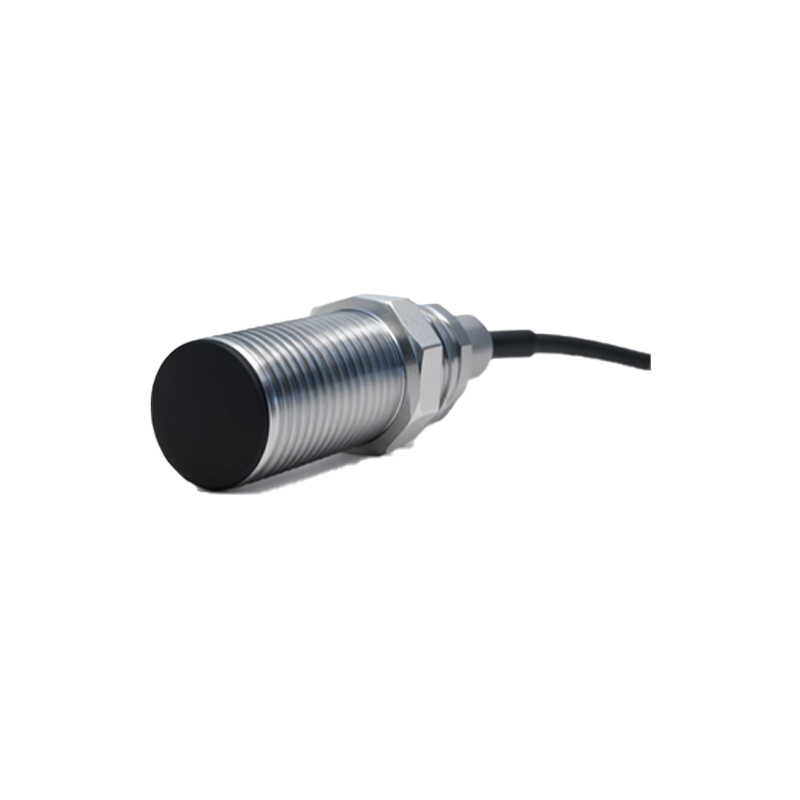
When connecting the output, match it to the input of the controller (e.g., PLC). NPN sensors sink current to ground, common in Europe and Asia, while PNP sensors source current from positive, preferred in North America. Incorrect pairing can cause malfunction. For example, an NPN sensor requires a sinking input on the PLC. If unsure, check the controller’s manual.
Mounting also affects wiring. Ensure the sensor is securely installed at the correct distance from the target. Metallic objects can influence inductive sensors, while capacitive sensors detect non-metallic materials. Avoid placing wires near motors or high-voltage cables to prevent electromagnetic interference. After wiring, test the sensor with a target object and verify the output using a multimeter or indicator light.
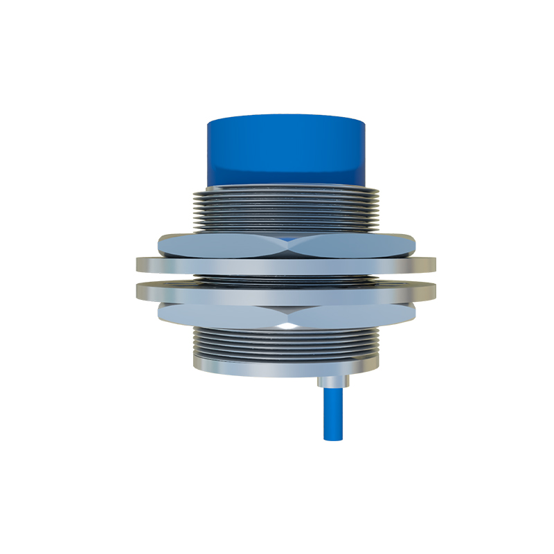
Common mistakes include reversed polarity, overloading the output, or using an incompatible power supply. These errors can lead to sensor failure or erratic behavior. Regular maintenance, such as cleaning the sensing face and checking wire insulation, prolongs sensor life. In summary, correct wiring involves understanding sensor specifications, following safety protocols, and testing thoroughly. By adhering to these practices, you can ensure optimal performance in automation systems.