As a seasoned electrical engineer specializing in industrial automation, I often encounter proximity switches in various control systems. These non-contact sensors are pivotal for detecting the presence or absence of metallic objects without physical contact, ensuring reliability in harsh environments. Today, I will conduct a detailed internal teardown of a typical inductive proximity switch, explaining its components, working principles, and design considerations.
The sensor under examination is a standard cylindrical inductive proximity switch with an M18 threaded body, commonly used in manufacturing lines. Before disassembly, ensure the device is disconnected from any power source to avoid electrical hazards. Using precision tools, carefully unscrew the front sensing face and the rear cable gland. The outer housing, usually made of nickel-plated brass or stainless steel, provides robust protection against mechanical stress and environmental factors like dust, moisture, and chemical exposure.
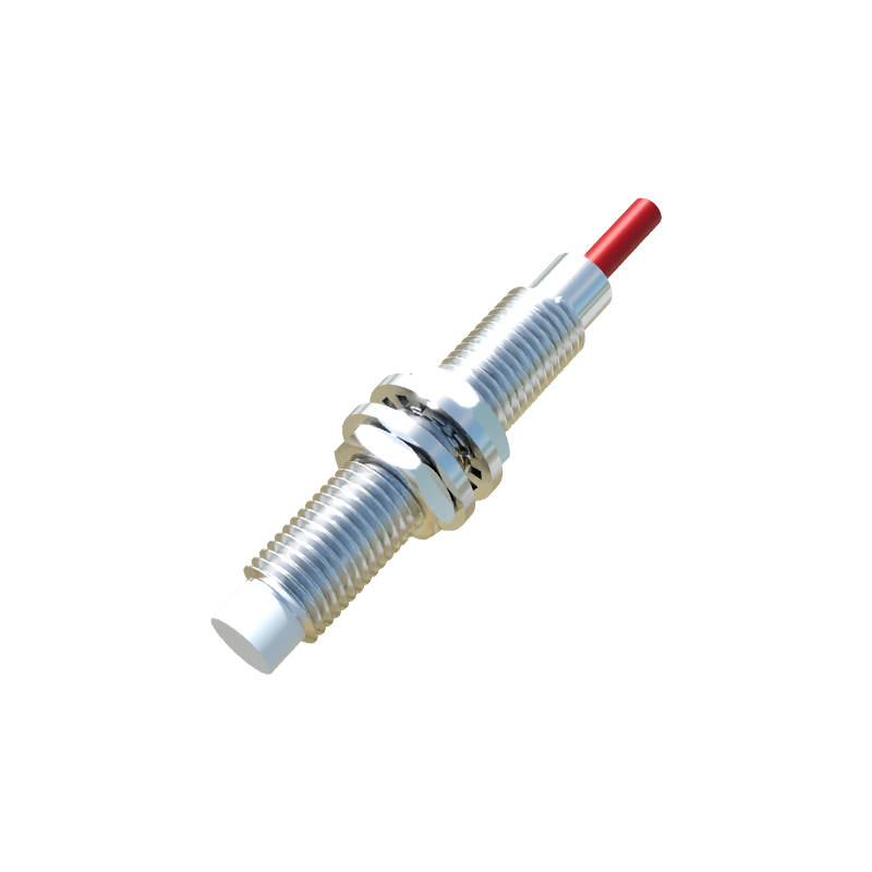
Inside, the core assembly reveals a multi-layered structure. At the forefront is the sensing coil, wound around a ferrite core. This coil generates a high-frequency electromagnetic field when energized. When a metallic target enters this field, eddy currents are induced in the target, causing a change in the coil's oscillation amplitude. This change is detected by the subsequent circuitry. The coil is encapsulated in epoxy resin to prevent movement and dampen vibrations, ensuring consistent performance.
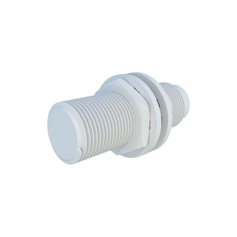
Behind the coil, a printed circuit board (PCB) houses the oscillator, demodulator, and output switching components. The oscillator typically operates at frequencies between 100 kHz to 1 MHz, creating the alternating magnetic field. The demodulator circuit converts the amplitude variation into a DC signal. This signal then triggers the output stage, which may consist of a transistor (for DC models) or a triac (for AC models), providing a switch signal to the connected controller. Surface-mount technology (SMT) is widely used on the PCB to minimize size and enhance reliability. Notably, some advanced models include diagnostic LEDs and short-circuit protection circuits, visible as tiny integrated circuits and resistors on the board.
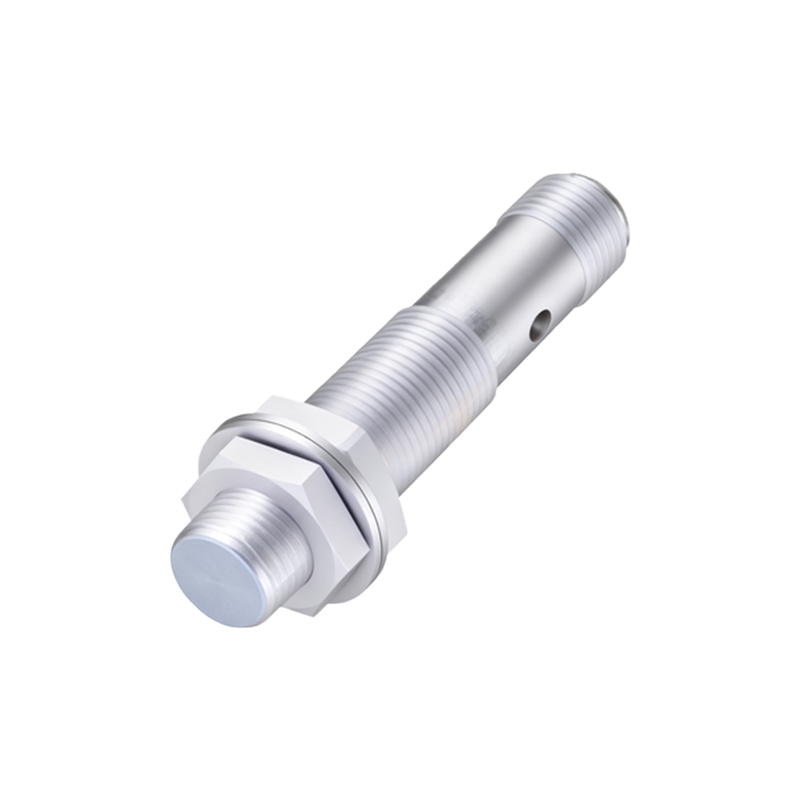
Further inspection shows a shielding can surrounding the PCB, made of mu-metal or similar material, to block external electromagnetic interference (EMI). This is critical in industrial settings with high noise from motors or frequency drives. The cable entry point includes strain relief and sealing gaskets, maintaining the IP67 or higher ingress protection rating.
The internal design emphasizes durability and precision. For instance, the coil's winding density and core material are optimized for specific sensing ranges, typically from 2 mm to 15 mm for standard models. Engineers select ferrite cores for their high magnetic permeability, which enhances sensitivity. Additionally, the housing's thread design allows for easy mounting in panels, while the epoxy filling ensures thermal stability across operating temperatures from -25°C to 70°C.
In summary, this teardown highlights the sophisticated engineering behind proximity switches. From the robust housing to the sensitive electronic components, each part plays a role in delivering accurate, non-contact detection. Understanding these internals aids in proper selection, installation, and troubleshooting, ultimately improving system uptime in automation applications. For maintenance, always refer to manufacturer guidelines to avoid damaging the sealed components.