In the realm of industrial automation and control systems, proximity sensors are indispensable components for detecting the presence or absence of objects without physical contact. A critical, yet often overlooked, aspect of their specification and integration is determining the appropriate power rating. Selecting a sensor with an incorrect power rating can lead to premature failure, unreliable operation, or even damage to connected systems. This article delves into the key considerations for choosing the right power for your proximity sensor application.
First, it is essential to understand that the "power" of a proximity sensor typically refers to its electrical supply requirements and its own power consumption, not an output power in the mechanical sense. The primary specifications are the supply voltage range and the current draw. Most industrial proximity sensors operate on standard DC voltages (e.g., 10-30 VDC) or AC voltages (e.g., 90-250 VAC). The power rating must be compatible with the available plant voltage to ensure stable operation.
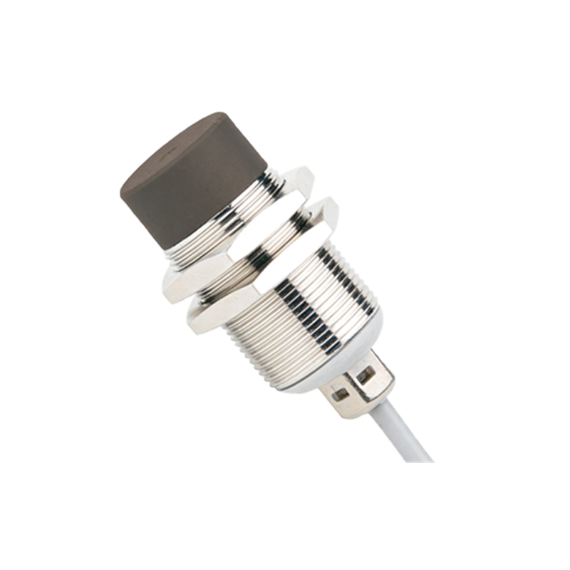
The sensor's current consumption is a direct factor in its power demand. This is usually specified in the datasheet as the maximum current draw or no-load current. For instance, a standard 2-wire DC sensor might have a leakage current of 1.8 mA, while a 3-wire DC sensor's supply current could be below 20 mA. This consumption, while seemingly small, must be factored into the capacity of the power supply, especially when multiple sensors are connected to a single source. An undersized power supply will cause voltage drops, leading to sensor malfunction.
The load connected to the sensor's output also significantly influences the power considerations. For switching outputs (like NPN/PNP transistors or relay contacts), the datasheet specifies a maximum switching current and voltage. Exceeding these limits can destroy the output circuit. For example, a sensor with a 200mA switching capacity cannot reliably control a load drawing 300mA. It is crucial to calculate the total load (including inrush currents for inductive loads like solenoids or contactor coils) and ensure it falls within the sensor's rated capacity. Using an external relay or an interposing device is a common practice for handling higher-power loads.
Environmental conditions play a substantial role. Ambient temperature is a major factor. A sensor operating at its maximum rated temperature will often have a derated switching capacity. The datasheet will provide derating curves. High temperatures increase internal resistance and can reduce the effective output current the sensor can handle safely. Similarly, in applications with significant voltage fluctuations or electrical noise (common in plants with large motors), choosing a sensor with a wide operating voltage range and robust surge protection is a form of "power rating" consideration for reliability.
Another key aspect is the duty cycle. While many sensors are rated for continuous operation, some high-speed or pulsed applications require checking the maximum switching frequency and ensuring the sensor's internal components can dissipate the heat generated from rapid switching without exceeding thermal limits.
So, what is the "right" power? There is no single answer. It is a system-level decision. Follow this practical approach:
1. Identify System Voltage: Confirm the available supply voltage (e.g., 24 VDC).
2. Check Sensor Consumption: From the candidate sensor's datasheet, note its maximum supply current.
3. Calculate Total Load: Determine the current and voltage requirements of the device the sensor will switch (the load).
4. Apply Safety Margins: Ensure the sensor's switching specifications exceed the load requirements by at least 15-20%. For the power supply, sum the current draw of all sensors and loads, then select a supply with a capacity 30-50% higher.
5. Consider Environment: Apply derating factors for high-temperature applications and ensure voltage range compatibility.
For example, in a 24VDC system controlling a small relay coil with a steady-state current of 50mA and a 100mA inrush, a standard 3-wire PNP sensor with a 100mA switching capacity would be insufficient at startup. A sensor rated for 200mA or the use of a protective circuit would be necessary.
In conclusion, the "right" power rating for a proximity sensor is not merely about matching a voltage number. It is a holistic evaluation of supply compatibility, sensor self-consumption, load characteristics, environmental stresses, and prudent engineering safety margins. Always consult and thoroughly understand the manufacturer's datasheet—it is the ultimate authority on the device's electrical capabilities. Proper power matching ensures longevity, reliability, and safety in your automated processes, preventing costly downtime and replacements.