In industrial automation and control systems, 24V DC metal proximity sensors are ubiquitous components, prized for their reliability, non-contact operation, and durability in harsh environments. These inductive sensors detect the presence of ferrous metals (like steel and iron) without physical contact, making them ideal for position sensing, counting, and limit switching. However, their effectiveness hinges entirely on correct installation and wiring. Incorrect wiring can lead to sensor failure, damage to connected controllers like PLCs, or unsafe operational conditions. This guide provides a comprehensive, step-by-step approach to wiring a standard 3-wire DC metal proximity sensor, ensuring a safe and functional installation.
Before handling any electrical components, the paramount rule is safety. Always disconnect and lock out all power sources to the circuit and equipment. Verify the absence of voltage using a multimeter. Wear appropriate personal protective equipment (PPE). Ensure you have the sensor's datasheet; while color codes are often standard, manufacturers can vary. The three wires are typically:
Brown: Connected to the positive DC supply voltage (+24V).
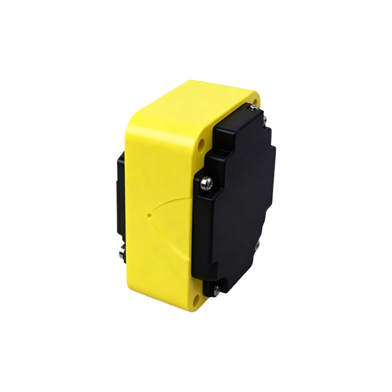
Blue: Connected to the negative DC supply voltage (0V or Common).
Black: The output signal wire. For an NPN (sinking) sensor, this wire sinks current to ground when active. For a PNP (sourcing) sensor, this wire sources current from the positive supply when active.
The first critical step is identifying your sensor's type: NPN or PNP. This defines how the output interacts with your load (e.g., a PLC input, relay, or indicator lamp). Check the sensor housing for markings like "NPN/NO" or "PNP/NC" or consult the datasheet. Most industrial PLCs in Europe and many globally are designed for PNP (sourcing) inputs, while NPN is common in some Asian markets. Using the wrong type for your controller will result in the signal not being read.
For a standard 3-wire DC sensor, you will need a 24V DC power supply, the sensor, your load (e.g., a PLC digital input module), and appropriate wiring tools. A typical wiring procedure is as follows:
1. Prepare the Wires: Strip a small section of insulation from the ends of the sensor's brown, blue, and black wires.
2. Connect Power: Connect the BROWN wire to the positive terminal (+24V) of your DC power supply. Connect the BLUE wire to the negative terminal (0V/Common) of the same power supply. This provides the operating voltage for the sensor's internal electronics.
3. Connect the Output (Load): This step depends on your sensor type.
For a PNP Sensor: The black wire is the positive output. When a metal target is detected, it sources +24V. Connect the BLACK wire to one side of your load (e.g., terminal of a PLC input channel). Connect the other side of the load to the power supply's negative (0V/Common). The load is now between the sensor output and ground.
For an NPN Sensor: The black wire is the negative output. When active, it sinks current to ground. Connect the BLACK wire to one side of your load. Connect the other side of the load to the positive terminal (+24V) of the power supply. The load is now between the positive supply and the sensor output.
4. Verify Connections: Double-check all connections for tightness and correctness. Ensure no stray wire strands could cause a short circuit.
Once wiring is complete and visually verified, you can proceed to power up and test. Restore power to the DC supply. Most proximity sensors have an LED indicator. Bring a piece of the appropriate metal (usually mild steel) within the sensor's specified sensing distance. The LED should illuminate (or change state) upon detection. Simultaneously, use your multimeter to measure the voltage between the sensor's black wire and the blue (0V) wire. For a PNP sensor, it should read close to +24V when active. For an NPN sensor, it should read close to 0V when active. Finally, confirm that your connected load (PLC input, relay) activates as expected.
Several common pitfalls can undermine performance. Never connect the sensor directly to an AC mains supply, as this will destroy it. Ensure the power supply voltage is stable and within the sensor's rated range (typically 10-30V DC). Pay close attention to the sensing characteristics: the rated sensing distance is for a standard mild steel target; other metals like aluminum or stainless steel have reduction factors. Maintain adequate clearance around the sensor head, as metallic objects in the side or rear can affect performance.