In industrial automation and machinery applications, proximity sensors play a critical role in detecting the presence or absence of objects without physical contact. Among these, the 13 series proximity sensors are widely utilized due to their robustness and reliability. However, like any electronic component, they are susceptible to failure under certain conditions. This article delves into the common causes, symptoms, and troubleshooting steps for a damaged 13 proximity sensor, providing insights for engineers and technicians to ensure operational efficiency.
A 13 proximity sensor typically operates on inductive or capacitive principles, generating an electromagnetic field to detect metallic or non-metallic targets. When functioning correctly, it ensures seamless automation processes, but failure can lead to costly downtime and safety hazards. The primary indicators of a damaged sensor include inconsistent output signals, complete loss of detection, or erratic behavior in connected systems. For instance, a machine might stop unexpectedly or fail to initiate cycles, often traced back to sensor malfunction.
Several factors contribute to the failure of 13 proximity sensors. Environmental conditions are a major culprit; exposure to excessive moisture, dust, or corrosive substances can degrade internal components over time. In high-temperature settings, thermal stress may cause solder joints to crack or electronic circuits to overheat, leading to permanent damage. Mechanical issues, such as physical impact or vibration, can also dislodge sensor elements or fracture housings. Additionally, electrical problems like voltage spikes, incorrect wiring, or power supply fluctuations can overwhelm the sensor's circuitry, resulting in burnout or short circuits.
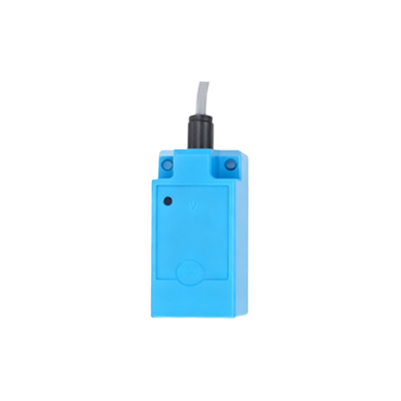
To diagnose a faulty 13 proximity sensor, start with a visual inspection. Check for obvious signs of damage, such as cracks, corrosion, or loose connections. Ensure the sensor is properly mounted and aligned with its target, as misalignment can mimic failure symptoms. Next, use a multimeter to test the power supply and output signals. A healthy sensor should show stable voltage levels within the specified range, typically 10-30V DC for most models. If the output fails to switch states when a target is presented, it may indicate internal failure. For inductive sensors, verify the sensing distance; a reduced range often points to weakened electromagnetic fields due to component wear.
In cases where the sensor appears functional but causes system errors, consider interference from external sources. Electromagnetic interference (EMI) from nearby motors or high-frequency devices can disrupt sensor signals. Shielding cables or relocating the sensor might resolve such issues. Regular maintenance, including cleaning and calibration, can prevent premature failure. For persistent problems, consult the manufacturer's datasheet for specific tolerances and replacement guidelines.
Replacing a damaged 13 proximity sensor involves selecting a compatible model with matching specifications, such as sensing type, voltage, and output configuration. Always power down equipment before installation to avoid electrical hazards. After replacement, conduct thorough testing to ensure proper integration with the control system. Documenting failures and solutions can aid in predictive maintenance, reducing future downtime.
In summary, while 13 proximity sensors are durable, they are not immune to damage. By understanding failure modes and implementing proactive troubleshooting, engineers can maintain optimal performance in industrial settings. Prioritize environmental protection, correct installation, and regular checks to extend sensor lifespan and uphold safety standards.