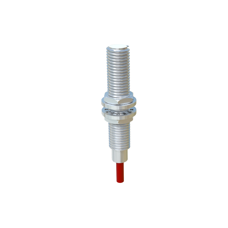
In industrial automation and control systems, proximity sensors are indispensable components for detecting the presence or absence of objects without physical contact. Among various types, 4-wire proximity sensors are widely used due to their versatility and reliability. This article provides a comprehensive guide to the wiring diagram, installation, and operation of 4-wire proximity sensors, tailored for electrical engineers and technicians.
A 4-wire proximity sensor typically consists of two power supply wires and two output wires. The power supply wires connect to a DC voltage source, commonly 12-24V DC, which energizes the sensor's internal circuitry. The output wires provide a switched signal based on the detection state. There are two main output configurations: NPN (sinking) and PNP (sourcing). In NPN configuration, the output wire connects to the load, and the load is connected to positive voltage, allowing current to sink to ground when activated. In PNP configuration, the output wire sources current from the positive supply to the load, which is then connected to ground. Understanding these configurations is crucial for proper integration into control systems.
The wiring diagram for a 4-wire proximity sensor follows a standardized color-coding scheme, though variations may exist by manufacturer. Typically, brown wire is for positive voltage supply (+V), blue wire is for negative or ground (0V), black wire is for output signal (NO or NC), and white wire is often used for a complementary output or diagnostic function. For example, in a common setup with a PNP sensor: connect brown to +24V DC, blue to 0V ground, black to the input of a PLC or relay, and white may be left unused or configured per manual. Always refer to the sensor's datasheet for specific wiring instructions, as incorrect connections can lead to malfunction or damage.
Installation of a 4-wire proximity sensor requires attention to environmental factors. Ensure the sensor is mounted securely, with the sensing face oriented correctly toward the target object. Maintain an appropriate sensing distance, typically specified as the nominal range, and avoid metallic interference from nearby objects. For inductive sensors, which detect metals, the target material (e.g., steel, aluminum) can affect the sensing range—steel provides the longest range, while non-ferrous metals may reduce it. Capacitive sensors, used for non-metallic objects, are sensitive to moisture and dust, so consider enclosures or protective measures in harsh conditions.
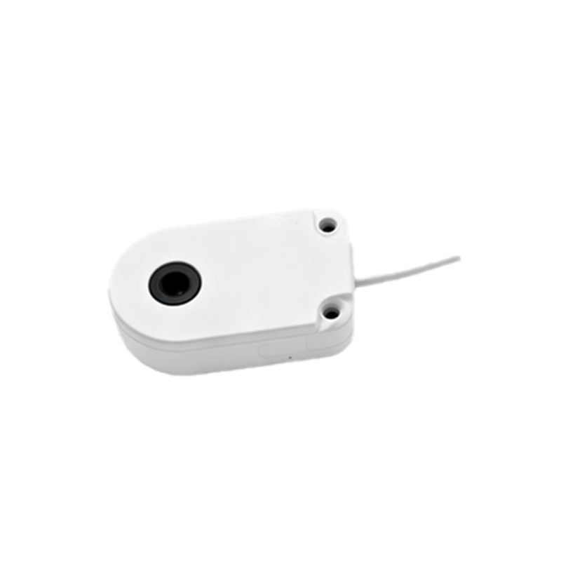
Troubleshooting common issues involves checking the wiring connections, power supply voltage, and output load compatibility. Use a multimeter to verify voltage at the sensor terminals: brown-blue should show the rated DC voltage (e.g., 24V), and black-blue should indicate 0V when inactive and near supply voltage when active (for PNP). If the sensor fails to trigger, inspect for misalignment, target size (which should be at least the sensor's face diameter), or electrical noise from motors or cables. Shielding and proper grounding can mitigate noise interference.
In summary, 4-wire proximity sensors offer flexible integration into automated systems, with clear wiring diagrams and robust performance. By following manufacturer guidelines and understanding the NPN/PNP outputs, engineers can ensure reliable operation. Regular maintenance, such as cleaning the sensing face and checking connections, prolongs sensor life and enhances system efficiency. As technology advances, features like IO-Link communication in some 4-wire sensors enable smart diagnostics and parameter adjustments, further optimizing industrial processes.