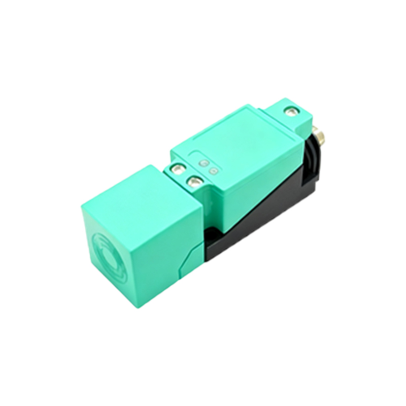
BDUK photoelectric proximity sensors are widely used in industrial automation for detecting objects without physical contact. These sensors operate by emitting a light beam and measuring the reflection or interruption to determine the presence, absence, or distance of an object. Proper wiring is crucial for ensuring reliable operation and safety in various applications, such as conveyor systems, packaging machinery, and robotic cells. This guide provides a detailed overview of the wiring diagram for BDUK photoelectric proximity sensors, covering key components, connection steps, and best practices.
BDUK photoelectric sensors typically come in three main types: through-beam, retro-reflective, and diffuse reflective. Each type has specific wiring requirements, but the fundamental principles remain similar. The sensor generally includes the following terminals: power supply (V+ and V-), output signal (NO/NC), and ground. For most BDUK models, the wiring diagram is labeled directly on the sensor housing or provided in the datasheet. A standard wiring setup involves connecting the sensor to a power source and a control device, such as a programmable logic controller (PLC) or relay.
To wire a BDUK photoelectric proximity sensor, start by identifying the voltage requirements. Common models operate on DC 10-30V or AC 20-250V. Check the sensor's specifications to match the power supply. For DC sensors, connect the positive wire (usually brown) to V+ and the negative wire (blue) to V-. The output wire (black or white) should be linked to the load device. If using a normally open (NO) configuration, the output activates when an object is detected; for normally closed (NC), it deactivates. Ensure proper grounding by connecting the ground terminal (green/yellow) to earth to prevent electrical noise and interference.
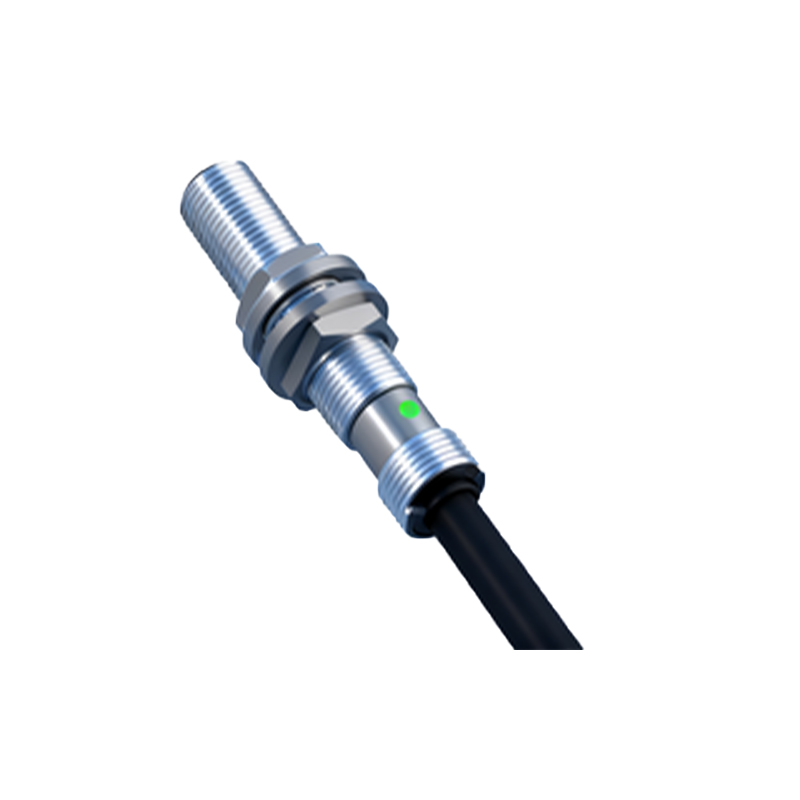
In industrial environments, shielding and cable management are essential. Use shielded cables to reduce electromagnetic interference (EMI), especially in areas with high-frequency equipment. Route cables away from power lines and motors to avoid signal degradation. For through-beam sensors, align the emitter and receiver precisely to maintain optimal performance. Test the sensor after wiring by placing an object within its sensing range and verifying the output signal with a multimeter or PLC input indicator. Adjust the sensitivity potentiometer if available to fine-tune detection.

Common wiring mistakes include incorrect polarity, loose connections, and overloading the output. Always double-check the wiring diagram before powering the system. For complex installations, refer to BDUK's technical documentation or consult an expert. Regular maintenance, such as cleaning the lens and inspecting cables, ensures long-term reliability. By following these guidelines, you can integrate BDUK photoelectric proximity sensors effectively into your automation systems, enhancing efficiency and safety.