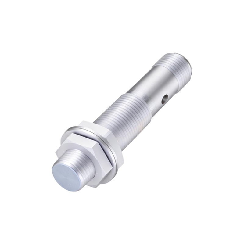
Magnetic proximity sensors are fundamental components in industrial automation, safety systems, and countless electromechanical applications. Their ability to detect the presence or absence of a ferromagnetic target without physical contact makes them robust, reliable, and maintenance-free. For an electrical engineer, understanding the schematic diagram is key to proper selection, integration, and troubleshooting. This article delves into the core principles and typical schematic representations of common magnetic proximity sensor types.
At its heart, a magnetic proximity sensor operates by reacting to changes in a magnetic field. The most prevalent technology is the reed switch-based sensor. Its schematic symbol is straightforward, typically depicted as two overlapping, flexible ferromagnetic reeds enclosed within a glass capsule. These reeds are normally open (NO) or sometimes normally closed (NC). The schematic shows the switch contacts in their resting state. When a permanent magnet (the target) approaches within the specified sensing distance, the reeds magnetize, attract each other, and make contact, closing the circuit. The schematic for the connected circuit would show the sensor contacts in series with the load (e.g., a PLC input, relay coil, or indicator lamp) and the power supply. A crucial element often included in the system schematic is a protective component, such as a flyback diode or an RC snubber network, connected in parallel with the inductive load (like a relay coil) to suppress voltage spikes generated when the reed switch opens, protecting the contacts from arcing and premature wear.
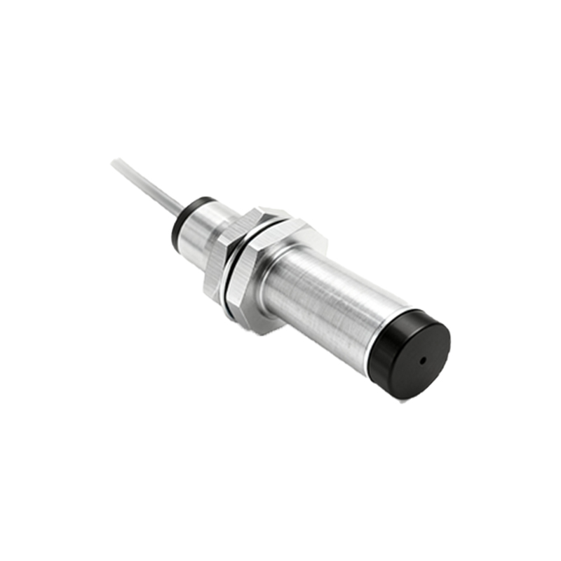
A more advanced and widely used type is the solid-state Hall-effect sensor. Its schematic diagram is more complex, representing an integrated circuit. The core symbol often includes a small rectangle with the letter "H" or a stylized representation of the Hall plate. The schematic will detail the necessary external connections: supply voltage (Vcc, typically 5V, 12V, or 24V DC), ground (GND), and the output signal. Hall sensors can have digital (open-collector or push-pull) or analog outputs. A common digital output schematic shows an NPN transistor whose collector is the output pin. This transistor is internally controlled by the Hall element. When no magnetic field of sufficient strength (south pole for most sensors) is present, the output transistor is off (open-collector high impedance). When a target magnet approaches, the Hall voltage triggers the comparator inside the IC, turning the transistor on and pulling the output line low (to near ground). The schematic must include a pull-up resistor (e.g., 10kΩ) connected between the output pin and Vcc for the open-collector type to define a high logic level when the transistor is off. For a 3-wire DC PNP type sensor, the output transistor is a PNP, sourcing current to the load.
Wiring diagrams are integral to the schematic understanding. A standard 3-wire DC sensor schematic clearly labels: Brown wire (+V), Blue wire (0V/GND), and Black wire (Output). The load is connected between the Black wire (for NPN) and +V, or between Black wire (for PNP) and GND. For 2-wire AC/DC sensors, the schematic shows the sensor acting as a variable impedance switch directly in series with the AC line or DC supply and the load. Here, a minimum holding current is a critical parameter shown in datasheets.
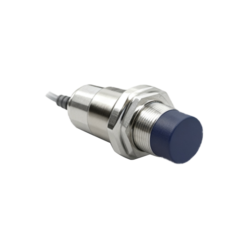
Key parameters reflected in or inferred from schematic analysis include the sensing distance, hysteresis (the difference between switch-on and switch-off points to prevent chatter), output type (NO/NC, NPN/PNP), and supply voltage range. Engineers must also consider the interface with the control system. Connecting an NPN sensor to a PLC sinking input, for instance, requires careful review of the combined schematic to ensure proper current flow.
In conclusion, the schematic diagram of a magnetic proximity sensor is not just a symbolic representation; it is a functional map that reveals the sensor's technology, electrical characteristics, and integration requirements. Whether it's the simple elegance of a reed switch or the sophisticated electronics of a Hall-effect IC, mastering the schematic allows engineers to deploy these sensors effectively, ensuring reliable operation in demanding industrial environments. Always cross-reference the schematic with the manufacturer's datasheet for specific ratings, wiring instructions, and application notes.