Proximity sensors are indispensable components in modern industrial automation, playing a critical role in object detection, positioning, and counting without physical contact. Their correct wiring is fundamental to ensuring system reliability, safety, and optimal performance. This guide provides a comprehensive, step-by-step explanation of proximity sensor wiring, complete with diagrammatic illustrations and best practices for installation.
Understanding Proximity Sensor Types and Outputs
Before connecting wires, identifying the sensor type and its output configuration is crucial. The two primary categories are based on the detection principle: Inductive (for detecting metallic objects) and Capacitive (for detecting both metallic and non-metallic objects). Furthermore, sensors are classified by their output circuitry:
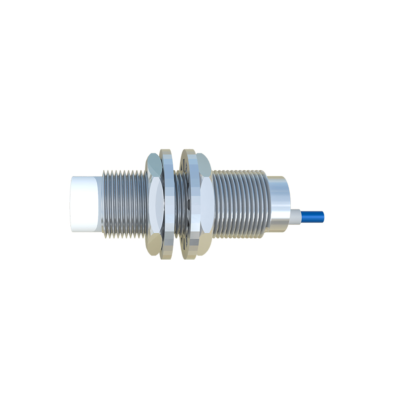
1. NPN (Sinking) Output: The load is connected between the sensor's output wire (usually black) and the positive supply voltage (+V). The sensor acts as a switch to ground (0V). Common in European and Asian designs.
2. PNP (Sourcing) Output: The load is connected between the sensor's output wire and the ground (0V). The sensor acts as a switch to the positive supply (+V). Predominant in North American applications.
3. Analog Output: Provides a continuously variable voltage or current signal proportional to the distance to the target.
4. NAMUR Output: A two-wire, intrinsically safe design used in hazardous areas, requiring a separate switching amplifier.
Standard 3-Wire DC Sensor Wiring (NPN & PNP)
Most industrial DC proximity sensors follow a 3-wire configuration. The standard wire color coding, though not universal, is commonly:
Brown (or Red): Connected to the positive DC supply voltage (+V, typically 10-30V DC).
Blue (or Black): Connected to the DC common or ground (0V).
Black (or White/Blue): The output signal wire. Its behavior depends on whether the sensor is NPN or PNP.
Wiring Diagram and Step-by-Step Procedure
Diagram Reference: Imagine a simple schematic. On the left, a DC power supply symbol (e.g., 24V DC) is shown. The positive terminal connects to the sensor's brown wire. The negative terminal connects to the sensor's blue wire and one side of the load (e.g., a PLC input, relay coil). The sensor's black output wire connects to the other side of the load.
Step 1: Power Supply Verification. Always confirm the sensor's operating voltage range (e.g., 10-30V DC). Ensure your power supply matches this and is correctly fused. Disconnect power before starting any wiring work.
Step 2: Connecting Power Wires. Connect the brown wire to the positive (+) terminal of your DC power source. Connect the blue wire to the negative (-) or 0V terminal of the same power source. This provides the sensor with the necessary operating power. Use ferrules or properly stripped and secured wire ends.
Step 3: Connecting the Output Load (Critical Step). This step differentiates NPN from PNP wiring.
For an NPN Sensor: The black wire is the switched negative. Connect one terminal of your load (e.g., PLC input card point X0) to the positive supply (+V). Connect the other terminal of the load to the sensor's black wire. When a target is detected, the NPN transistor switches on, connecting the load to 0V (Blue), completing the circuit and activating the load.
For a PNP Sensor: The black wire is the switched positive. Connect one terminal of your load to the ground/0V (Blue wire common). Connect the other terminal of the load directly to the sensor's black wire. Upon detection, the PNP transistor switches on, supplying +V (Brown) to the load, thus activating it.
Step 4: Load Compatibility. Verify that the sensor's maximum output current rating is not exceeded by the load's current draw. For heavy loads like large contactor coils, always use an intermediate relay.
2-Wire DC Sensor Wiring
Two-wire sensors are simpler, acting like a switch in series with the power line and the load. They have only two wires, typically brown and blue. The brown wire connects to +V, and the blue wire connects to one side of the load. The other side of the load connects to 0V. It is vital to ensure there is always a minimum "leakage current" through the load when the sensor is off, or the sensor may not function correctly. Always check the manufacturer's datasheet for minimum load requirements.
Shielded Cable and Noise Immunity
For