In industrial automation and control systems, the reliable interface between sensing devices and actuating components is fundamental. A common and critical task for electrical engineers and technicians is wiring a proximity sensor to a control relay. This setup forms the backbone of countless automated processes, from conveyor belt control and machine guarding to part counting and position detection. This guide provides a detailed, step-by-step explanation of the wiring process, focusing on standard 3-wire DC proximity sensors and single-pole relays, while highlighting key considerations for safety and reliability.
First, it is crucial to understand the components. A typical inductive or capacitive proximity sensor (often rated 10-30V DC) has three wires: Brown (or Red) for the positive supply voltage (+V), Blue (or Black) for the common negative (0V or GND), and Black (or White) for the switched output signal. The relay is an electromechanical or solid-state device with a coil (the input) and one or more contact sets (the output). The coil voltage must match the sensor's supply voltage (e.g., 24V DC). The relay's common (COM), normally open (NO), and normally closed (NC) contacts will connect to the load, such as a motor starter coil, solenoid valve, or PLC input.
The core wiring principle is to use the proximity sensor's output to control the power flow to the relay coil. Here is the standard procedure:
1. Power Supply Connection: Establish a stable DC power source, for example, 24V DC. Connect the positive terminal (+) of the power supply to the Brown wire of the proximity sensor. Connect the negative terminal (-) of the power supply to the Blue wire of the sensor. This provides operating power to the sensor's internal circuitry.
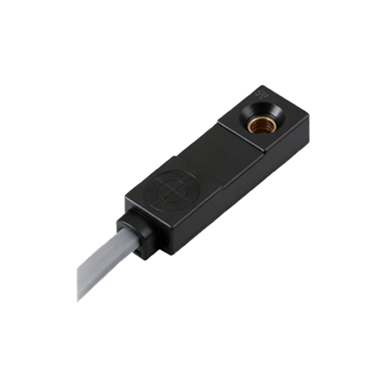
2. Relay Coil Connection (The Critical Link): The relay coil now needs to be placed in series with the sensor's output. There are two common methods:
Sourcing (PNP) Sensor Configuration: If your sensor is a PNP type (sourcing output), the Black output wire switches the positive voltage. Connect the Black wire from the sensor to one terminal of the relay coil. Connect the other terminal of the relay coil directly back to the negative terminal (-) of the power supply (the same point as the sensor's Blue wire).
Sinking (NPN) Sensor Configuration: If your sensor is an NPN type (sinking output), the Black output wire switches the negative path. Connect one terminal of the relay coil to the positive terminal (+) of the power supply. Connect the other terminal of the relay coil to the Black wire of the sensor. The sensor's Blue wire is already connected to the power supply negative.
Important: Always verify your sensor's type (PNP or NNP) from its datasheet or label before wiring. Incorrect connection will not activate the relay.
3. Load Connection via Relay Contacts: The relay's contacts are now used to safely switch the actual load, which often operates at a different, potentially higher voltage (e.g., 120V AC for a motor). For a simple on/off control using a Normally Open (NO) contact:
Connect the hot wire (e.g., L1 for AC) of the load's power circuit to the relay's COM terminal.
Connect the relay's NO terminal to one side of the load (e.g., the motor coil).
The other side of the load connects back to the neutral (for AC) or the return path of its own power supply.
This isolates the low-voltage sensor circuit from the high-power load circuit, which is a primary safety function of the relay.
4. Protection and Best Practices:
Flyback Diode: When driving an electromechanical relay coil, always install a flyback diode (like a 1N4007) in reverse bias across the coil terminals (anode to negative, cathode to positive). This suppresses voltage spikes generated when the coil de-energizes, protecting both the sensor's output transistor and other sensitive electronics.
Fusing: Install appropriate fuses on both the sensor power supply line and the load power circuit.
Shielded Cable: Use shielded cable for the sensor in electrically noisy environments, grounding the shield at one end to the control panel earth.
Testing: Before applying full power, use a multimeter to check for short circuits. After powering, verify that the sensor's indicator LED activates when a target is present and that the relay audibly clicks. Confirm the load switches as intended.
Troubleshooting common issues often involves checking the basics: Is power present