In the realm of industrial automation and control systems, proximity switches and photoelectric sensors are fundamental components, serving as the critical "eyes" and "touch" of machinery. These devices provide non-contact object detection, enabling precise, reliable, and high-speed operations in diverse and often harsh environments. This guide delves into the operational principles, types, key specifications, and application considerations for these essential sensors.
Understanding Proximity Switches
Proximity switches, or proximity sensors, detect the presence or absence of a target object without physical contact. They operate based on changes in an electromagnetic field. The most common types are inductive and capacitive.
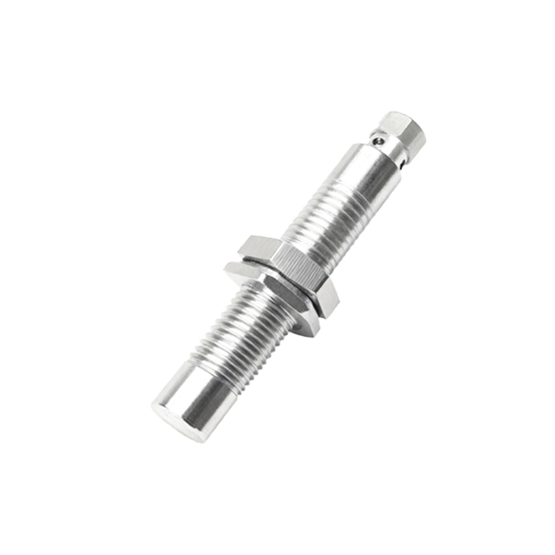
Inductive Proximity Sensors: These sensors generate an oscillating electromagnetic field. When a metallic object (ferrous or non-ferrous) enters this field, it induces eddy currents within the target, causing a change in the oscillation amplitude. The sensor's internal circuit detects this change and triggers a solid-state switch. They are ideal for detecting metals and are highly resistant to environmental contaminants like dust, oil, and coolant.
Capacitive Proximity Sensors: These sensors can detect both metallic and non-metallic materials (plastics, wood, liquids, granules) by sensing changes in capacitance. The sensor forms one plate of a capacitor, the target object forms the other, and the air gap is the dielectric. As a target approaches, the capacitance increases, and the sensor triggers once a preset threshold is reached. They are perfect for level detection, material handling, and presence sensing of non-metals.
Decoding Photoelectric Sensors
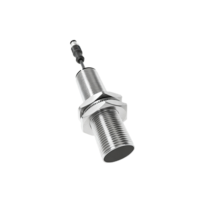
Photoelectric sensors use light to detect objects. They consist of a light emitter (usually an LED) and a receiver. Detection is based on the presence, absence, or modulation of the light beam. Their key advantage is long sensing ranges and the ability to detect virtually any material.
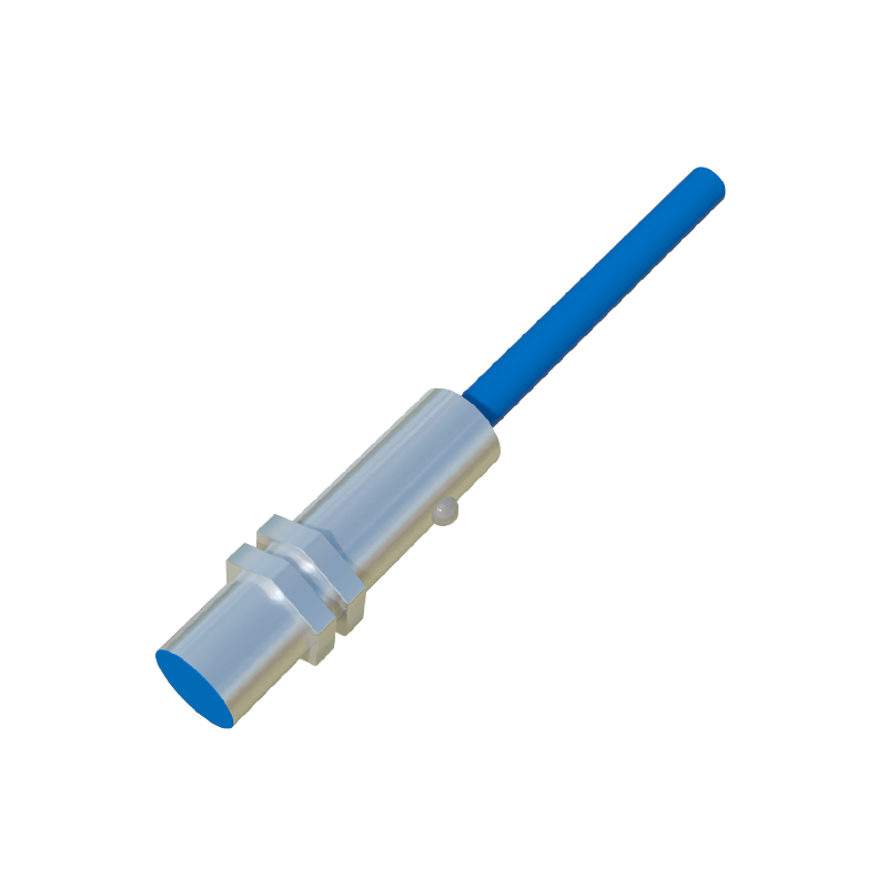
The three primary operating modes are:
1. Through-Beam (Opposed): The emitter and receiver are in separate housings facing each other. An object is detected when it interrupts the light beam. This mode offers the longest range and highest reliability, as it is less sensitive to target color, reflectivity, or surface angle.
2. Retroreflective: The emitter and receiver are in the same housing. A reflector (corner-cube prism) is placed opposite the sensor. The emitted light bounces off the reflector back to the receiver. An object is detected when it breaks this reflected beam. This mode simplifies wiring but requires a clean reflector.
3. Diffuse (Proximity): The emitter and receiver are in the same housing. Detection occurs when the emitted light hits a target and a sufficient amount of scattered (diffuse) light is reflected back to the receiver. Sensing distance depends heavily on the target's size, color, and surface texture. Advanced versions use background suppression or fixed-field teaching to ignore objects beyond a set distance.
Key Technical Specifications and Selection Criteria
Choosing the right sensor is critical for system performance. Key parameters include:
Sensing Distance: The nominal operating distance. For proximity sensors, this is typically a fraction of an inch to several inches. For photoelectric sensors, it can range from a few millimeters to hundreds of meters for through-beam types.
Repeatability: The consistency of the detection point under identical conditions.
Response Time: The speed at which the sensor can detect an object and change its output state. Crucial for high-speed counting or sorting applications.
Output Type: Common outputs include NPN/PNP transistor (sinking/sourcing), analog (4-20mA, 0-10V), and IO-Link for digital communication and parameterization.
Environmental Rating: Ingress Protection (IP) ratings (e.g., IP67, IP69K) define resistance to dust and water. Temperature range, chemical resistance, and housing material (e.g., stainless steel, PBT plastic) are also vital for harsh environments.
Target Characteristics: For proximity sensors: material type and size. For photoelectric: color, reflectivity, transparency, and surface finish.
Application Best Practices and Troubleshooting
Proper installation and maintenance ensure longevity and reliability.
Mounting: Ensure the sensor is securely mounted to prevent vibration-induced errors. For inductive sensors, maintain clearance from surrounding metal (flush vs. non-flush mounting). For photoelectric sensors, avoid mounting where ambient light (sunlight, welding arcs) can interfere.
Electrical Considerations: Adhere to voltage specifications. Use shielded cables in electrically noisy environments and ensure proper grounding. Install surge protectors if connected to inductive loads like solenoids or motors.
Troubleshooting Common Issues:
No