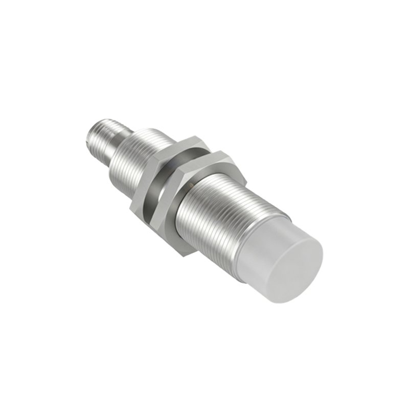
Proximity sensors are essential components in modern industrial automation, providing non-contact detection of metallic or non-metallic objects. Proper wiring is critical to ensure reliable operation, safety, and longevity of these sensors. This guide offers a comprehensive overview of proximity sensor wiring diagrams, covering common types, configurations, and best practices for installation.
Proximity sensors are typically categorized into three main types based on their detection principle: inductive, capacitive, and photoelectric. Inductive sensors detect metallic objects, capacitive sensors detect both metallic and non-metallic materials, and photoelectric sensors use light beams for detection. Each type has specific wiring requirements, but most share common wiring principles.
A standard three-wire DC proximity sensor includes three terminals: brown (positive), blue (negative), and black (output). The brown wire connects to the positive DC supply voltage, usually ranging from 10 to 30 VDC. The blue wire connects to the DC common or ground. The black wire is the output signal wire, which switches to either supply voltage (PNP configuration) or ground (NPN configuration) when an object is detected. In PNP (sourcing) sensors, the output provides positive voltage to the load. In NPN (sinking) sensors, the output connects the load to ground.
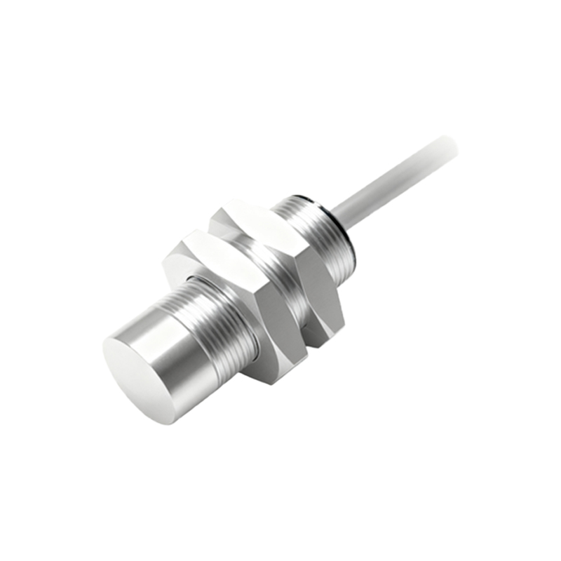
For two-wire AC/DC sensors, wiring is simpler: one wire connects to the power supply, and the other serves as both power and output. However, these sensors may have higher leakage current, which can affect some control systems. Always verify compatibility with the controller.
Shielded cables are recommended for long cable runs or electrically noisy environments to prevent electromagnetic interference. The cable shield should be grounded at one end only, typically at the control panel, to avoid ground loops. Ensure wires are properly insulated and secured using cable glands or strain relief fittings to prevent damage from vibration or pulling.
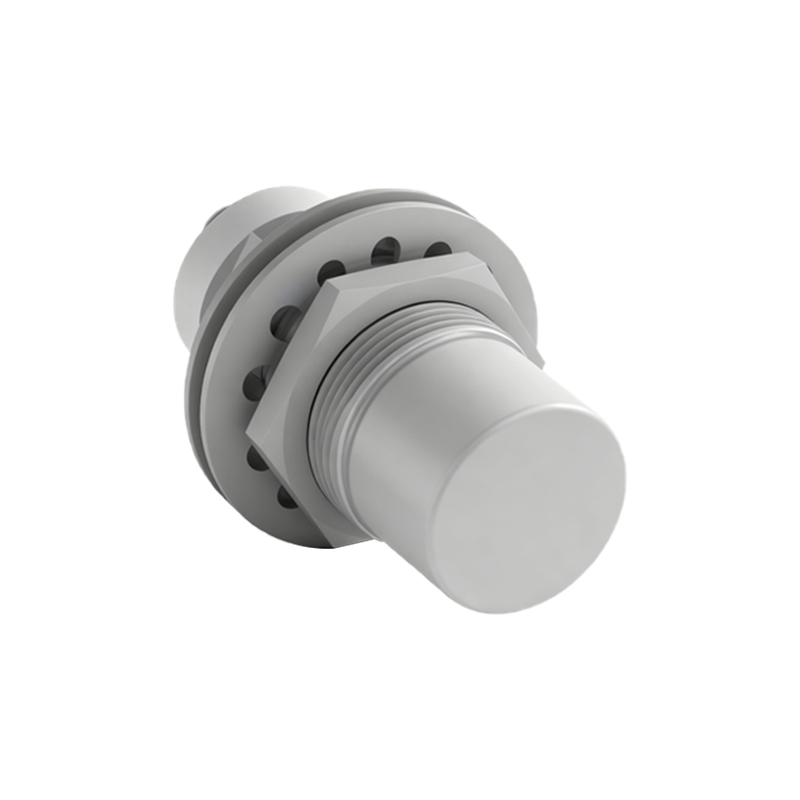
When connecting to a PLC (Programmable Logic Controller), match the sensor output type (PNP or NPN) with the PLC input type. PNP sensors work with sinking PLC inputs, while NPN sensors pair with sourcing inputs. Incorrect pairing can lead to malfunction or damage. Always refer to the manufacturer’s datasheet for voltage, current, and temperature ratings.
For hazardous locations, use intrinsically safe or explosion-proof sensors with appropriate barriers and conduits. Follow local electrical codes and standards, such as NEC, IEC, or ATEX, for safety compliance. Regular testing with a multimeter can diagnose wiring issues like short circuits, open circuits, or incorrect polarity.
In summary, understanding proximity sensor wiring diagrams ensures optimal performance in automation systems. Key steps include selecting the correct sensor type, matching wiring configurations, using proper shielding, and adhering to safety standards. With precise installation, these sensors enhance efficiency and reliability in diverse industrial applications.