In the realm of industrial automation and precision engineering, the measurement of angular position is a fundamental requirement for countless applications, from robotic arm articulation to valve positioning and rotary table control. While optical encoders and resolvers are traditional go-to solutions, proximity sensors offer a robust, contactless, and often more economical alternative for specific angle measurement scenarios. This article delves into the methodologies and practical considerations for measuring angles using proximity sensors.
The core principle behind angular measurement with proximity sensors relies on detecting the relative position or presence of a target attached to a rotating shaft or component. Unlike direct measurement devices that output an absolute or incremental angular value, proximity sensors typically provide a binary or analog signal indicating presence/absence or distance. Therefore, the system design must translate this basic information into an angular value. The most common approaches involve using multiple sensors or specially shaped targets.
One prevalent method is the use of a multi-pole or slotted target wheel. A ferrous or metallic wheel with precisely machined teeth or slots is mounted on the rotating shaft. An inductive proximity sensor is positioned such that it detects each passing tooth. By counting the pulses generated as the teeth pass the sensor, the system can calculate the rotational speed. To determine absolute angle within one revolution, a reference point is required. This is often achieved by incorporating a single, uniquely sized or positioned "home" tooth or gap on the target wheel. The sensor detects this distinct feature, providing a zero or reference position. The angular position is then interpolated from the pulse count relative to this home position. The resolution of this method depends directly on the number of teeth on the wheel.
For applications requiring higher resolution or continuous analog output, a shaped target cam is employed. In this configuration, the target's profile is carefully designed—often as an eccentric circle or a specially contoured lobe. A non-contact analog proximity sensor (inductive or capacitive) is fixed and measures the changing distance to the surface of this rotating cam. As the shaft rotates, the distance between the sensor face and the target surface varies in a precise, predetermined manner that is a function of the angle. The sensor's analog voltage or current output, which corresponds linearly to distance, thus becomes an analog representation of the angular position. This output curve must be meticulously calibrated. The relationship between distance and angle is defined by the cam's geometry, and the system's control logic must be programmed with this transfer function to convert the sensor signal into an accurate angle reading.
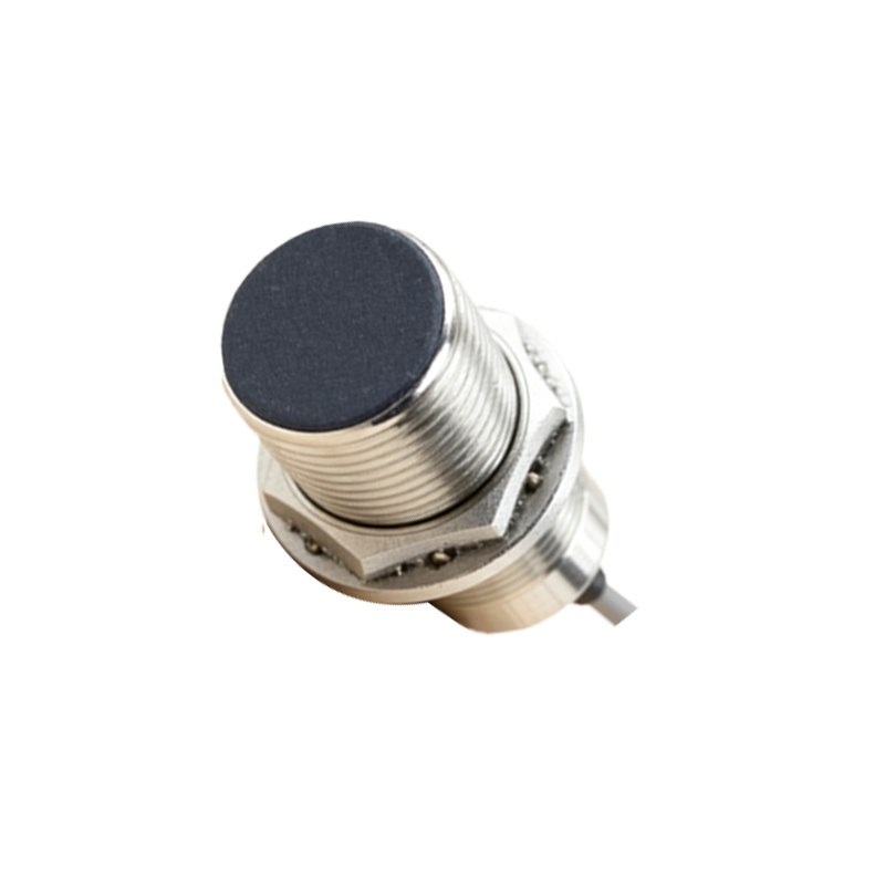
Another sophisticated technique involves arranging multiple proximity sensors in an array around the circumference of a standard cylindrical target or a specially encoded disc. For instance, three sensors spaced 120 degrees apart can be used to determine the orientation of a shaft by detecting asymmetries or markers. More complex arrangements, akin to a non-contact version of a potentiometer, can provide higher resolution. The key here is the signal processing algorithm that interprets the combined outputs from the sensor array to compute the precise angle.
Critical engineering considerations for implementing such a system are paramount. Sensor selection is the first step. Inductive sensors are ideal for ferrous metal targets, while capacitive sensors can detect non-metallic materials. The sensing range, frequency response (for high-speed rotation), and environmental robustness (against oil, coolant, or temperature extremes) must match the application. The precision of the target machining is equally crucial; any imperfection in tooth spacing or cam profile directly translates to measurement error. Mounting stability is non-negotiable—any vibration or shift in the sensor or target alignment will degrade accuracy.
Signal conditioning and interfacing with a Programmable Logic Controller (PLC) or microcontroller are the final links. For pulse-counting methods, high-speed counter modules are essential. For analog sensors, high-resolution analog-to-digital converters (ADCs) are required. The control system must execute the necessary calculations, whether it's simple pulse counting with reset or applying a complex geometric calibration curve to an analog input.
In conclusion, while not a direct replacement for high-end optical encoders in ultra-high-precision applications, proximity sensors provide a remarkably viable solution for angle measurement where cost, environmental durability, and simplicity are key drivers. Success hinges on a systems engineering approach: meticulously designing the target geometry, selecting the appropriate sensor technology, ensuring mechanical precision, and implementing reliable signal processing. This method exemplifies the innovative application of fundamental sensing technology to solve a classic engineering challenge.