Leveling the print bed is a critical step in achieving high-quality 3D prints. An unlevel bed leads to poor first-layer adhesion, warping, and print failures. While manual leveling with paper or feeler gauges is common, it can be time-consuming and inconsistent. Integrating a proximity sensor, such as an inductive or capacitive sensor, automates this process, enhancing precision and repeatability. This article details the methodology for implementing and calibrating a proximity sensor for automated bed leveling in FDM 3D printers.
Proximity sensors function by detecting the presence or distance of the bed without physical contact. Inductive sensors detect metallic surfaces, making them ideal for printers with a spring steel sheet or aluminum build plate. Capacitive sensors can detect both metallic and non-metallic surfaces, such as glass or BuildTak sheets, by measuring changes in capacitance. The core principle involves mounting the sensor on the printer's toolhead or a dedicated probe location. The sensor then takes multiple point measurements across the bed grid, and the printer's firmware uses this data to create a mesh map of the bed's topography. This mesh allows the firmware to dynamically adjust the Z-axis during printing, compensating for any deviations in flatness.
The installation process begins with selecting a compatible sensor. Key specifications include operating voltage (commonly 12V or 24V), sensing distance (typically 2-8mm), and output type (PNP/NPN). Ensure the sensor is compatible with your printer's mainboard and firmware, such as Marlin, Klipper, or RepRapFirmware. Mounting the sensor securely is paramount; any wobble or flex will introduce measurement errors. Use rigid brackets, preferably made of metal or reinforced plastic, to attach the sensor to the extruder assembly. The sensor should be positioned so its sensing face is parallel to the bed and at a consistent height relative to the nozzle. A common practice is to set the sensor's trigger point slightly lower than the nozzle's tip, allowing the firmware to calculate the precise nozzle-to-bed offset.
Wiring the sensor correctly is crucial for reliable operation. Connect the sensor's power leads to the appropriate voltage supply on the mainboard, often labeled "PROBE" or with a dedicated port. The signal wire connects to a designated probe input pin. Always consult your printer's wiring diagram to avoid damage. After physical installation, firmware configuration is the next critical phase. In Marlin, for example, you must enable features likeAUTO_BED_LEVELING_BILINEAR orAUTO_BED_LEVELING_UBL and define the probe settings:NOZZLE_TO_PROBE_OFFSET (the X, Y, and Z distances from the nozzle to the probe),Z_MIN_PROBE_PIN, andPROBING_MARGIN. TheGRID_MAX_POINTS_X andGRID_MAX_POINTS_Y settings determine the density of the measurement mesh; a 3x3 or 5x5 grid is standard.
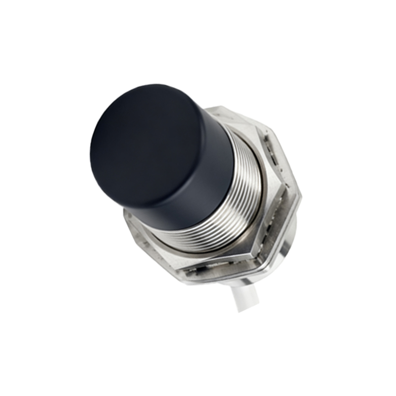
Calibration is a multi-step process to ensure accuracy. First, perform a manual rough leveling of the bed using traditional methods to bring it as close to level as possible. This provides a good starting point for the sensor. Next, you must determine the precise Z-offset—the distance between the sensor's trigger point and the actual nozzle height. This is done by homing the printer, deploying the probe, and then using a piece of paper or a feeler gauge at the bed's center. Adjust the Z-offset in the firmware until you feel slight friction between the nozzle and the gauge. Store this value in the firmware's EEPROM. Finally, initiate an automated bed leveling sequence via the printer's controller. The printer will probe the predefined grid points. After completion, save the mesh to memory and enable bed leveling compensation (e.g.,M420 S1 in G-code).
Regular maintenance and verification are essential. Over time, sensor performance can drift due to temperature changes, mechanical wear, or contamination. Periodically verify the Z-offset and re-run the bed leveling routine, especially after any hardware modifications. For inductive sensors, ensure the bed surface is clean and free of non-conductive debris. For capacitive sensors, environmental factors like humidity can affect readings; consider enclosing the printer for stability. Troubleshooting common issues involves checking wiring connections, verifying firmware settings, and ensuring the sensor is not triggered by unintended metallic parts (like screws or cables).
Implementing a proximity sensor for bed leveling transforms the 3D printing workflow. It reduces user intervention, increases first-layer consistency, and allows for successful prints on slightly warped beds. While the initial setup requires technical attention to detail, the long-term benefits in print reliability and time savings are