Proximity sensors are indispensable components in modern industrial automation, providing non-contact detection of metallic and non-metallic objects. Understanding their wiring configurations is crucial for ensuring reliable operation, safety, and system integration. This guide delves into the standard wiring diagrams for various proximity sensor types, offering practical insights for engineers and technicians.
The core function of a proximity sensor is to detect the presence or absence of an object within its sensing range without physical contact. They are primarily categorized by their output type: NPN (sinking) and PNP (sourcing), as well as by their technology: inductive (for metals), capacitive (for various materials including liquids), and ultrasonic. The wiring differs significantly between these types and must match the controller's input circuit, typically a Programmable Logic Controller (PLC) or a relay.
A standard three-wire DC sensor has leads for brown (positive supply +V), blue (common 0V), and black (output signal). For a PNP (sourcing) sensor, the black wire outputs a positive voltage (+V) when a target is detected. The typical wiring connects the brown wire to the DC positive supply, the blue wire to the DC negative or 0V, and the black output wire to the PLC's digital input. The PLC input module itself must be configured as a sinking type, completing the circuit to 0V internally. Conversely, an NPN (sinking) sensor sinks current to 0V when activated. Here, the brown and blue wires connect to +V and 0V as usual, but the black output wire connects to the PLC input. The PLC input module must be of the sourcing type, providing +V to the input, which the NPN sensor then sinks to 0V upon detection. Mismatching PNP and NPN sensors with the opposite PLC input type is a common installation error that results in non-operation.
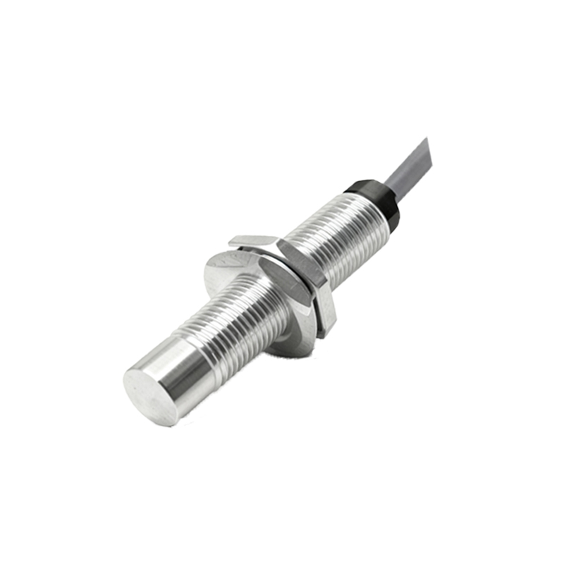
Two-wire AC/DC sensors simplify wiring by combining the supply and load in series, similar to a switch. They connect in series with the load (e.g., a PLC input or relay coil) to the power source. While convenient, attention must be paid to voltage drop and leakage current, which can sometimes cause a residual signal when the sensor is off.
Wiring diagrams also vary based on the output configuration: Normally Open (NO) or Normally Closed (NC). A NO contact closes (provides output) when a target is sensed, while an NC contact opens (stops output). This choice is critical for fail-safe design. For instance, in a safety-guard monitoring application, an NC configuration might be preferred so that a wire break is detected as a "target present" or fault condition.
Shielded cables are highly recommended, especially in environments with significant electromagnetic interference (EMI) from motors or frequency drives. The cable shield should be grounded at only one end, typically at the control panel, to prevent ground loops. Furthermore, for sensors in long cable runs or harsh environments, using surge suppressors or protective relays can prevent voltage spikes from damaging the sensor or controller.
A practical example involves integrating an inductive PNP NO proximity sensor with a PLC. The brown wire connects to +24VDC, the blue to 0VDC. The black wire connects to the PLC's digital input terminal (e.g., DI1). The corresponding PLC common for that input group is connected to 0VDC. When a metal object enters the sensing field, the sensor switches its internal transistor, sourcing +24V from the black wire into the PLC input, registering a logic HIGH.
For capacitive sensors used in level detection, the wiring is identical in principle, but mounting and grounding require extra care. The sensor body must be properly grounded, and the sensing face should be kept free from buildup to prevent false triggering.
In conclusion, correctly interpreting and implementing proximity sensor wiring diagrams is foundational to automation system integrity. Always consult the manufacturer's datasheet for specific wiring details, voltage ranges, and connection diagrams. Key practices include verifying supply polarity, matching sensor output (PNP/NPN) with the load input, implementing proper shielding, and choosing NO/NC configurations to achieve the desired control logic and safety functions. Proper wiring ensures not only functionality but also enhances the longevity and noise immunity of the entire control system.