In industrial automation and control systems, proximity sensors play a critical role in detecting the presence or absence of objects without physical contact. Among various types, 4-wire proximity sensors are widely used due to their versatility and reliability. This article provides a comprehensive guide to understanding the wiring diagram, installation, and operation of 4-wire proximity sensors, tailored for engineers and technicians in the electrical and automation fields.
A 4-wire proximity sensor typically consists of two power supply wires and two output wires. The power supply wires connect to a DC voltage source, commonly 12V DC or 24V DC, depending on the sensor model. The output wires are responsible for transmitting the detection signal to a control device, such as a programmable logic controller (PLC) or relay. The key advantage of a 4-wire sensor is its ability to provide both normally open (NO) and normally closed (NC) outputs, offering flexibility in circuit design.
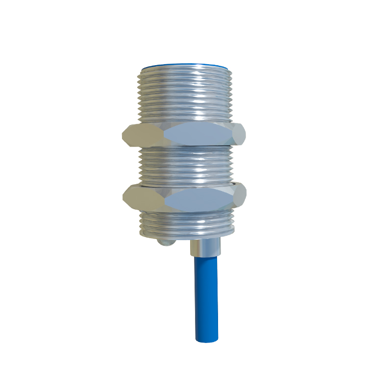
The wiring diagram for a 4-wire proximity sensor is straightforward but requires attention to detail to ensure proper functionality. First, identify the wire colors according to the manufacturer's datasheet. Typically, the brown wire is for positive voltage supply (+V), the blue wire is for negative or ground (0V), the black wire is for the normally open output, and the white wire is for the normally closed output. To wire the sensor, connect the brown wire to the positive terminal of the power supply and the blue wire to the negative terminal. Then, based on the desired output configuration, connect either the black wire (for NO) or the white wire (for NC) to the input terminal of the control device. The unused output wire should be insulated to prevent short circuits.
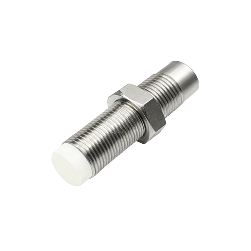
Installation of a 4-wire proximity sensor involves several best practices. Ensure the sensor is mounted securely in a location where it can accurately detect the target object. The sensing distance, as specified in the datasheet, should be maintained to avoid false triggers. Additionally, consider environmental factors such as temperature, humidity, and electromagnetic interference, which can affect sensor performance. For example, in high-vibration environments, use mounting brackets to stabilize the sensor. Always follow the manufacturer's guidelines for wiring and installation to prevent damage and ensure longevity.
Operation and troubleshooting are essential aspects of working with 4-wire proximity sensors. Once wired, test the sensor by bringing a target object within its sensing range. The output should activate the control device accordingly. If the sensor fails to operate, check the power supply voltage with a multimeter to ensure it matches the sensor's requirements. Verify all connections for loose wires or incorrect polarity. Common issues include incorrect wiring, insufficient power, or sensor misalignment. Regular maintenance, such as cleaning the sensor face and inspecting cables, can prevent operational failures.
In summary, 4-wire proximity sensors are integral components in automation systems, offering reliable object detection with flexible output options. By understanding the wiring diagram, adhering to installation guidelines, and performing routine checks, engineers can optimize sensor performance and enhance system efficiency. For specific applications, always refer to the sensor's technical documentation to tailor the setup to your needs.