Proximity switches and photoelectric sensors are fundamental components in modern industrial automation, providing non-contact detection for various applications such as object positioning, counting, and safety interlocks. Proper wiring is critical to ensure reliable operation, system safety, and longevity of these devices. This guide outlines standard wiring practices for common types of photoelectric sensors and proximity switches, focusing on DC 3-wire and 4-wire configurations prevalent in industrial settings.
Most industrial photoelectric sensors and inductive/capacitive proximity switches operate on DC voltages, typically 10-30 VDC. The three primary wiring configurations involve NPN (sinking) and PNP (sourcing) outputs, alongside a two-wire AC/DC variant. Understanding the difference between NPN and PNP is paramount. An NPN output sensor switches the negative (0V) line to the load. In a typical NPN 3-wire setup, the brown wire connects to the positive supply voltage (+V), the blue wire to the common negative (0V), and the black wire is the switched output. When the sensor detects an object, it connects the black output wire to the blue wire (0V), completing the circuit to the load (e.g., a PLC input). Conversely, a PNP output sensor switches the positive line. Here, the brown wire is +V, blue is 0V, and the black output wire provides the switched positive voltage to the load when activated.
For a standard 4-wire DC sensor, which often includes both a normally open (NO) and a normally closed (NC) output, the wiring expands. Typically, brown is +V, blue is 0V, black is the NO output, and white is the NC output. This allows for greater flexibility in control logic. It is essential to consult the specific sensor's datasheet, as wire color codes can vary by manufacturer, though the brown/blue convention for power is widely adopted per IEC standards.
Shielded cable is strongly recommended for sensor wiring, especially in environments with significant electromagnetic interference (EMI) from motors, drives, or welding equipment. The cable shield should be grounded at the control panel end only to prevent ground loops. Always ensure proper separation between sensor cables and high-voltage power lines. Conduit or cable trays should be used for mechanical protection.
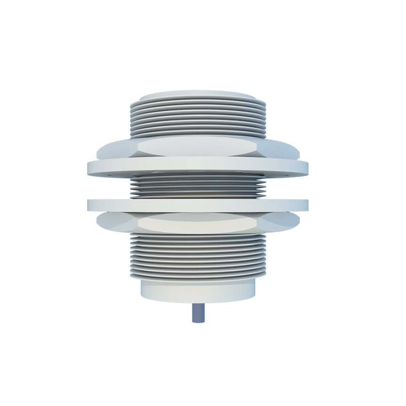
The load connected to the sensor output, usually a programmable logic controller (PLC) input, a relay coil, or an indicator lamp, must be compatible with the sensor's output type and current rating. Never exceed the sensor's maximum switching current. For PLC connections, verify if the PLC input module is designed for sinking (NPN-compatible) or sourcing (PNP-compatible) inputs. Mismatching an NPN sensor with a sourcing PLC input, or vice versa, will result in malfunction. A simple pull-up or pull-down resistor can sometimes resolve compatibility issues, but designing the system with matched components is the best practice.
For long cable runs, voltage drop must be calculated. Using a wire gauge that is too small for the distance can lead to insufficient voltage at the sensor, causing erratic behavior. As a rule of thumb, for a 24VDC system, consider increasing the wire size for runs exceeding 100 meters. Always implement proper fusing or circuit protection on the supply line to the sensor. A fast-acting fuse rated just above the sensor's inrush current is ideal.
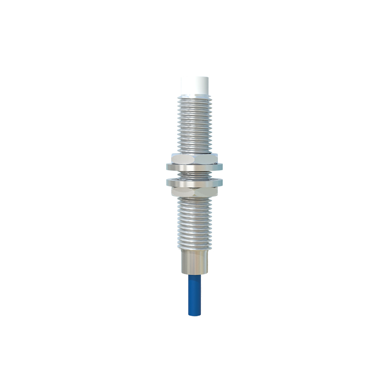
Finally, after wiring, perform a systematic check: verify power supply polarity and voltage, inspect for loose connections or pinched wires, and test the sensor's operation with its target object. Many sensors feature an LED indicator that shows both power status and output activation, which is invaluable for diagnostics. Proper installation and wiring not only prevent immediate failures but also reduce downtime over the long term, ensuring smooth and efficient automation processes.
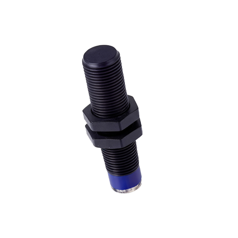
SEO Keywords:photoelectric sensor wiring, proximity switch wiring, NPN PNP sensor, industrial sensor installation, DC sensor wiring
SEO Description:A comprehensive guide on wiring proximity switches and photoelectric sensors in industrial systems. Covers NPN vs. PNP outputs, 3-wire and 4-wire configurations, EMI protection, PLC compatibility, and best practices for reliable automation.