Proximity sensors are essential components in modern industrial automation, enabling non-contact detection of objects within a specified range. These devices operate based on various physical principles, each suited to specific applications and environmental conditions. By examining principle diagrams, engineers can gain a deeper understanding of how proximity sensors function, select the appropriate type for their needs, and troubleshoot issues effectively.
One common type is the inductive proximity sensor, which detects metallic objects. Its principle diagram typically includes an oscillator coil, a demodulator, and an output circuit. When a metal object enters the electromagnetic field generated by the oscillator, eddy currents are induced in the object, causing a change in the oscillation amplitude. This change is detected by the demodulator, which triggers the output circuit to switch states. Inductive sensors are widely used in manufacturing for position sensing, counting, and safety applications due to their robustness and reliability in harsh environments.
Capacitive proximity sensors, on the other hand, can detect both metallic and non-metallic materials, such as plastics, liquids, or wood. The principle diagram for a capacitive sensor features a capacitor formed by the sensor's electrode and the target object. As an object approaches, the capacitance between the electrode and the ground changes, altering the oscillation frequency in an internal circuit. This frequency shift is processed to activate the output. Capacitive sensors are ideal for level detection, material handling, and packaging industries, where versatility is key.
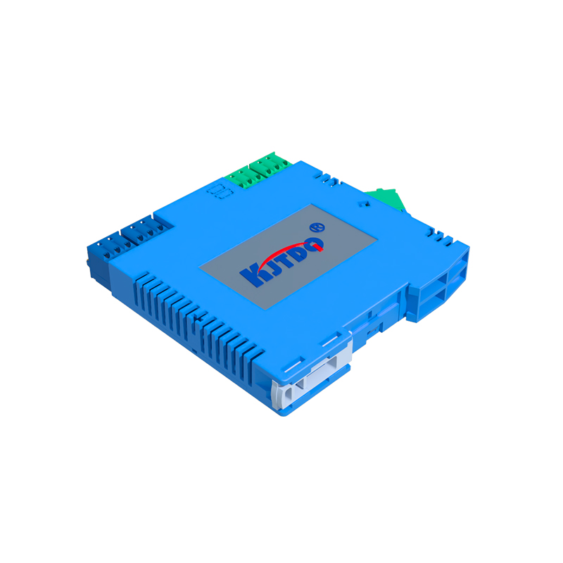
Ultrasonic proximity sensors utilize sound waves for detection, making them suitable for a wide range of materials and distances. A typical principle diagram shows a transmitter that emits high-frequency ultrasonic pulses and a receiver that listens for echoes. When an object interrupts the sound waves, the time delay between transmission and reception is measured to calculate distance. These sensors excel in applications requiring precise distance measurement or detection in challenging conditions, such as dusty or humid environments.
Photoelectric proximity sensors rely on light beams to detect objects. Their principle diagrams include a light source (often an LED or laser), a photodetector, and signal processing circuitry. When an object breaks or reflects the light beam, the photodetector senses the change, and the circuit produces an output signal. Photoelectric sensors are highly accurate and fast, commonly used in conveyor systems, robotics, and automated assembly lines for object presence or color detection.
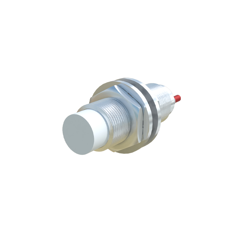
Magnetic proximity sensors, designed to detect permanent magnets, feature a reed switch or Hall effect sensor in their diagrams. When a magnet approaches, the magnetic field actuates the switch or generates a voltage in the Hall element, triggering the output. These sensors are favored in automotive and security systems for their simplicity and low power consumption.
Understanding these principle diagrams is crucial for optimizing sensor performance. Factors like sensing distance, response time, and environmental interference can be analyzed through the diagrams to ensure proper installation and maintenance. For instance, inductive sensors may have reduced range with non-ferrous metals, while capacitive sensors can be affected by humidity. By referring to diagrams, engineers can adjust settings or select shielding options to mitigate issues.
In practice, proximity sensors contribute to efficiency and safety across industries. From monitoring production lines to enabling touchless interfaces in consumer electronics, their non-contact nature minimizes wear and extends lifespan. As technology advances, new sensor types with integrated smart features, such as IO-Link connectivity, are emerging, offering enhanced diagnostics and configurability. Principle diagrams for these advanced sensors include digital communication modules, allowing real-time data exchange and remote control.
To summarize, proximity sensors are versatile tools in automation, each type with unique operating principles illustrated through diagrams. By studying these diagrams, professionals can make informed decisions, improve system reliability, and adapt to evolving industrial demands. Whether in simple presence detection or complex measurement tasks, proximity sensors continue to drive innovation, supported by clear visual representations of their inner workings.