Proximity switch sensors are indispensable components in modern industrial automation, offering non-contact detection of metallic and, in some cases, non-metallic objects. Their reliability directly impacts production line efficiency, equipment safety, and overall system uptime. To ensure optimal performance and longevity, adherence to specific installation, configuration, and maintenance protocols is paramount. This article outlines critical considerations for engineers and technicians working with these devices.
1. Environmental Considerations and Sensor Selection
The operating environment is the primary dictator of sensor selection and longevity. Key factors include:
Temperature: Exceeding the specified operating temperature range, typically -25°C to +70°C for standard models, can cause permanent damage to internal electronics or lead to erratic switching behavior. High-temperature environments require sensors with appropriate ratings or cooling strategies.
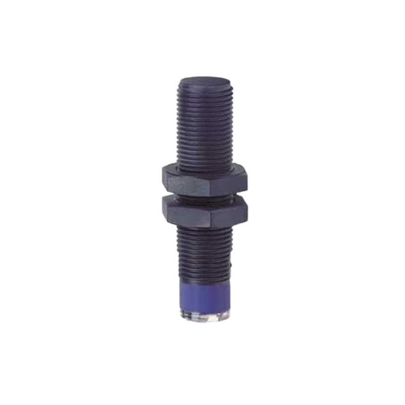
Contaminants: Dust, chips, coolant, and other conductive or non-conductive debris can accumulate on the sensor face, reducing its effective sensing range or causing false triggers. For harsh environments, select sensors with high IP (Ingress Protection) ratings (e.g., IP67, IP69K). Regular cleaning of the sensing face is essential.
Electromagnetic Interference (EMI): Install sensors away from high-frequency sources like variable frequency drives (VFDs), welding equipment, and large motors. Use shielded cables and ensure proper grounding of the sensor body and the control system to mitigate noise. Ferrous metal mounting brackets can sometimes help shield the sensor.
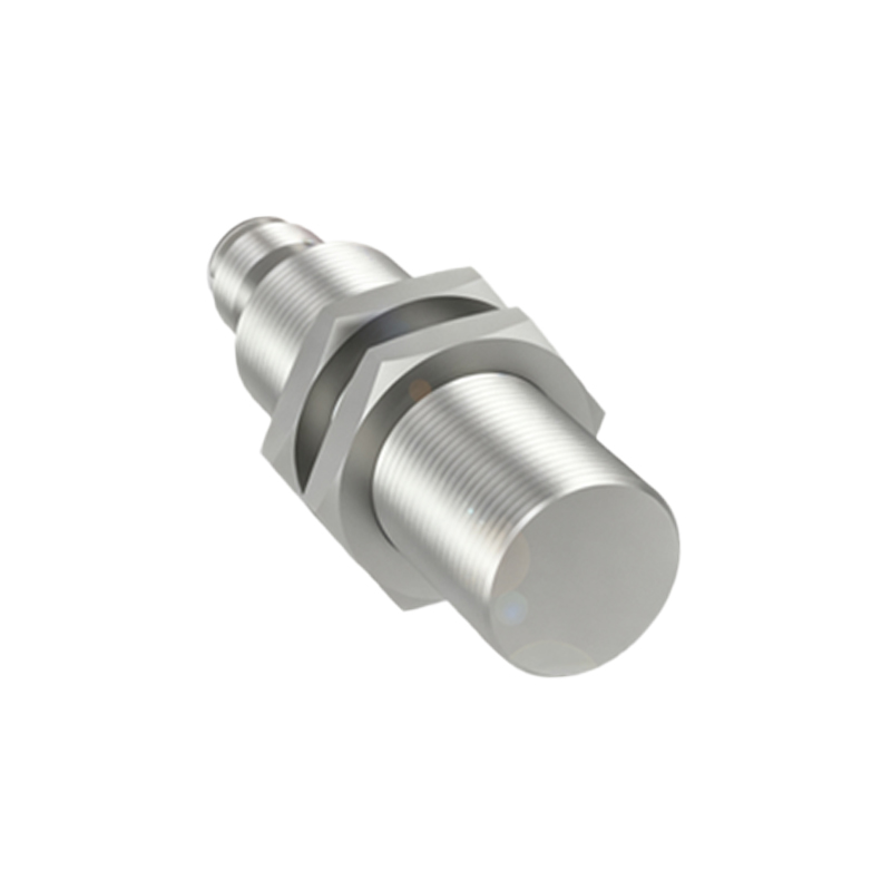
Target Material and Size: Inductive sensors detect ferrous and non-ferrous metals at different effective sensing distances (Sn). The standard rated operating distance is defined for mild steel. For other materials like aluminum, brass, or stainless steel, a correction factor (typically 0.3 to 0.9) must be applied. The target object must also be equal to or larger than the sensor's sensing face for reliable detection.
2. Installation and Mounting Precautions
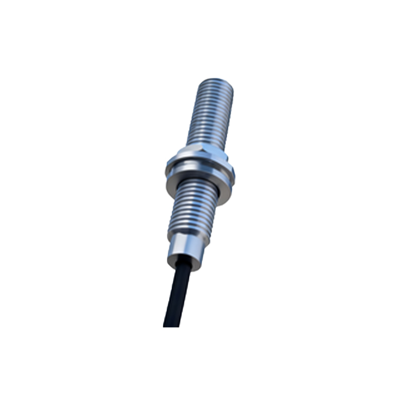
Proper mechanical installation is critical for reliable operation.
Mounting: Ensure the sensor is securely fastened using appropriate hardware to prevent vibration-induced loosening or misalignment. Avoid mounting multiple sensors directly opposite each other, as this can cause mutual interference or "crosstalk." Maintain a minimum lateral distance of at least twice the sensor diameter between adjacent sensors.
Sensing Direction and Alignment: The sensor must be aligned perpendicular to the expected path of the target object. Angular misalignment significantly reduces the effective sensing distance. For cylindrical barrel sensors, the recommended sensing direction is axial to the target's approach.
Flush vs. Non-Flush Mounting: Understand the difference. Flush-mountable (shielded) sensors can be embedded in metal without affecting performance but have a shorter range. Non-flush (unshielded) sensors offer a longer range but require a clear zone around the sensing face, free from surrounding metal, to function correctly.
Mechanical Stress: Avoid using the sensor's cable as a handling tool or subjecting it to excessive tension, twisting, or bending, especially at the cable entry point. Use cable glands or strain relief conduits. For applications with high vibration, consider sensors with ruggedized housings and M12 or M8 quick-disconnect connectors instead of fixed cables.
3. Electrical Wiring and Configuration
Incorrect wiring is a leading cause of sensor failure and control system issues.
Power Supply: Use a stable, regulated DC power supply within the sensor's specified voltage range (e.g., 10-30V DC). Ripple voltage should be minimal. Ensure the power supply has adequate current capacity for all connected sensors. Reverse polarity protection is common but not universal; always verify wiring against the datasheet.
Wiring Schemes (Sourcing vs. Sinking): Correctly identify the sensor's output type (PNP/NPN) and wire it compatibly with the PLC or controller input module. A PNP (sourcing) sensor switches the positive voltage to the load, while an NPN (sinking) sensor switches the negative side. Mismatching can damage the sensor or the controller.
Load and Protection: Do not exceed the sensor's maximum output current rating. For inductive loads (relays, solenoids), use a protective circuit like a flyback diode or a surge suppressor across the load to clamp voltage spikes that can destroy the sensor's output transistor.
Output State Indicators: Utilize the built-in LED indicator during setup and troubleshooting. A steadily lit LED typically indicates power and a target-in-range condition, while a blinking pattern may indicate an error or short-circuit condition (refer to manufacturer documentation).
4. Operational Testing and Maintenance
A proactive approach prevents unplanned downtime.
Initial Setup and Adjustment: After installation, power the system