Proximity sensors designed for glass detection are critical components in modern automation and safety systems. These sensors, often utilizing capacitive or ultrasonic principles, enable non-contact detection of glass surfaces in applications ranging from automotive windows and glass doors to industrial processing lines and smart appliances. Proper testing ensures reliability, prevents system failures, and maintains operational safety. This guide outlines systematic methods for testing glass proximity sensors, adhering to industry best practices.
First, understand the sensor type. Capacitive sensors detect changes in capacitance when glass (a dielectric material) enters their field. Ultrasonic sensors measure the time-of-flight of sound waves reflected off the glass surface. Confirm the sensor’s specifications—such as sensing distance, output type (PNP/NPN, analog, IO-Link), and supply voltage (typically 10-30V DC)—from the datasheet. Ensure the operating environment is free from excessive dust, moisture, or electromagnetic interference, which can affect readings.
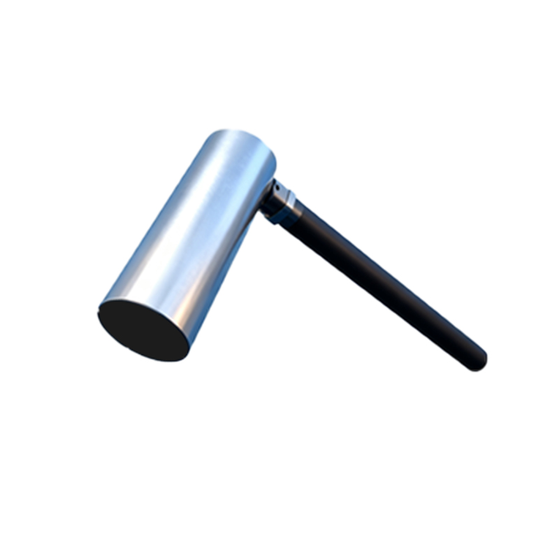
Begin testing with a visual inspection. Check for physical damage, corrosion, or misalignment. Verify that wiring connections are secure and compliant with the manufacturer’s diagram. Incorrect wiring is a common cause of sensor malfunction. Next, power the sensor using a regulated DC power supply within its voltage range. Observe the indicator LED (if present): a steady or blinking light often signifies normal operation, but refer to the manual for specific status codes.
For functional testing, use a calibrated glass sample matching the application’s thickness and composition. Position the sample within the specified sensing range. For capacitive sensors, note that detection can be influenced by the glass’s coating or tint; adjust sensitivity potentiometers if available. With ultrasonic sensors, ensure the surface is perpendicular to the sensor beam to avoid signal deflection. Monitor the sensor output using a multimeter or oscilloscope. For digital outputs, measure voltage between the signal wire and ground: a high signal (e.g., 24V) typically indicates detection, while a low signal (0V) indicates absence. Analog outputs should vary proportionally with distance; compare readings against the datasheet’s curve.
Perform repeatability tests by moving the glass sample in and out of the sensing zone multiple times. The sensor should consistently trigger within its rated hysteresis range. Test edge-case conditions, such as the minimum detectable thickness or maximum sensing distance, to validate performance limits. Environmental factors like temperature shifts or nearby metal objects can interfere; simulate these conditions if possible. For networked sensors, use diagnostic software to read parameters like signal strength or error logs.
Common issues include false triggering due to contamination on the sensor face, requiring cleaning with a soft cloth and isopropyl alcohol. If the sensor fails to detect, recalibrate sensitivity or check for power supply fluctuations. Persistent failures may necessitate replacement. Always document test results, including ambient conditions and output values, for maintenance records.
Regular testing as part of preventive maintenance schedules extends sensor lifespan. In critical applications, consider installing redundant sensors or using self-checking models with built-in diagnostics. Adhering to these testing protocols ensures accurate glass detection, enhancing system efficiency and safety in industrial and commercial settings.