In the realm of industrial automation and precise position sensing, Magnetic Proximity Hall Effect Sensors, particularly the 4-wire variant, have established themselves as indispensable components. These sensors offer a unique blend of reliability, non-contact operation, and environmental robustness, making them a preferred choice for engineers across diverse sectors. This article delves into the operational principles, key advantages, typical applications, and critical selection parameters for these sophisticated devices.
At its core, a 4-wire Hall effect proximity sensor operates on the fundamental principle discovered by Edwin Hall. When a conductor or semiconductor carrying a current is exposed to a perpendicular magnetic field, a voltage difference, known as the Hall voltage, is generated across it. In a proximity sensor, this conductor is a Hall effect IC. A permanent magnet is typically mounted on the moving target. As the target approaches the sensor, the magnetic field density at the Hall IC increases, triggering a change in its output state. The "4-wire" designation is crucial: it typically signifies two wires for the power supply (often denoted as Vcc and GND) and two separate output wires. This configuration commonly enables a dual output function, such as a Normally Open (NO) and a Normally Closed (NC) signal, or a complementary push-pull output, providing greater flexibility in control circuit design compared to 3-wire (PNP or NPN) types.
The advantages of using a 4-wire magnetic Hall sensor are numerous. First and foremost, their non-contact nature ensures virtually infinite mechanical life, as there is no physical wear between the sensor and the target. They are immune to contaminants like dust, oil, and moisture, which often plague optical or mechanical switches. They can operate at high speeds, detecting rapidly moving targets with precision. The solid-state Hall IC is also highly resistant to vibration and shock. The dual independent outputs from a 4-wire sensor allow for more complex logic control, fail-safe monitoring, or the simultaneous control of two different circuits based on a single sensed position. For instance, one output can activate a warning light as a machine part nears its endpoint, while the other can trigger a brake or reversal sequence upon actual arrival.
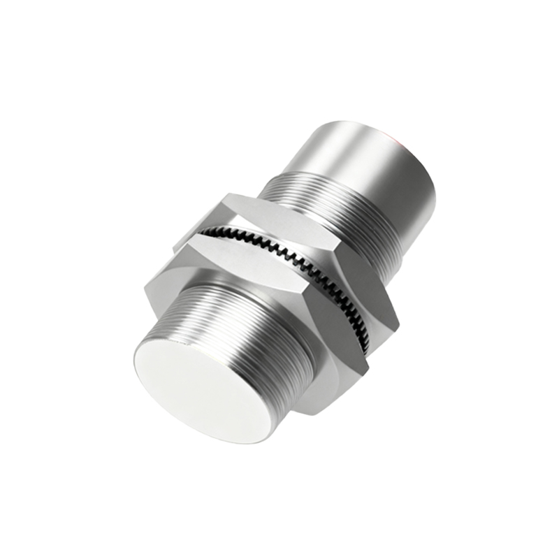
These sensors find extensive applications in harsh and demanding environments. Common use cases include:
Position and End-of-Travel Sensing: Detecting the open/closed status of valves, doors, or linear actuators.
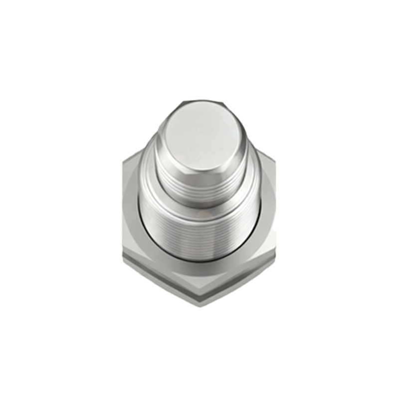
Rotary Speed Sensing: Measuring RPM by detecting passing gear teeth or magnetic poles on a shaft, critical in automotive crankshaft/camshaft positioning and industrial motor control.
Pneumatic Cylinder Position Feedback: Replacing traditional reed switches in cylinders for more reliable piston position indication.
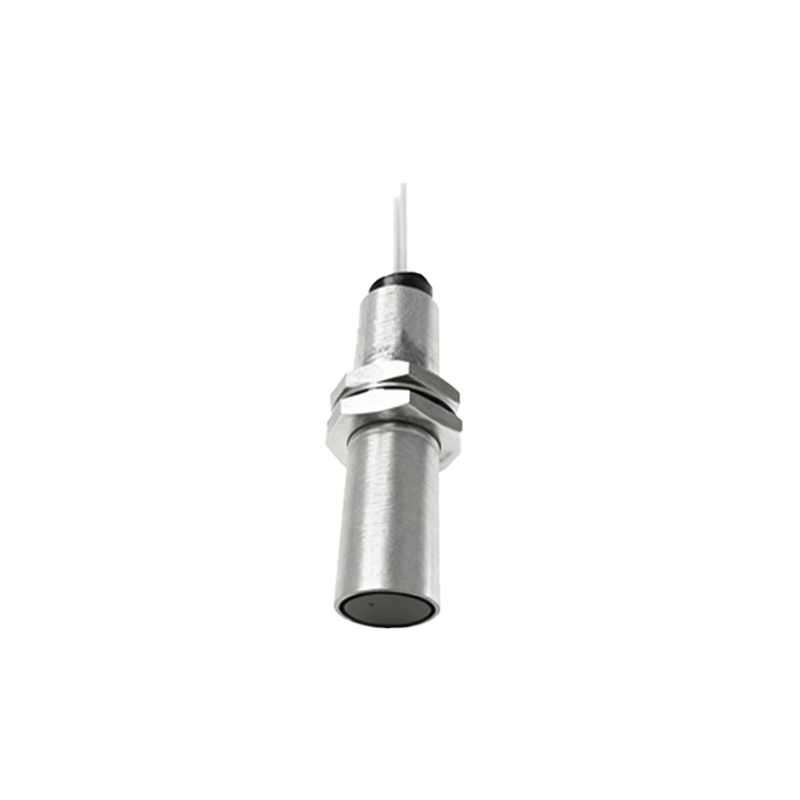
Material Handling: Detecting the presence of ferrous objects on conveyors or in automated storage systems.
Safety Interlocks: Ensuring guards or covers are securely in place before machinery can operate.
Selecting the right 4-wire magnetic proximity sensor requires careful consideration of several technical parameters:
1. Sensing Distance: The nominal operating distance at which the sensor reliably switches. This is influenced by magnet strength and size.
2. Output Type and Configuration: Confirm the output logic (e.g., sinking, sourcing, complementary) and the function of each wire (e.g., Brown: V+, Blue: V-, Black: NO output, White: NC output is a common color code).
3. Supply Voltage Range: Typically spans DC 5V to 30V, ensuring compatibility with the control system's power.
4. Output Current Rating: The maximum continuous current the output switch can handle, which must be sufficient for the connected load (e.g., PLC input, relay coil).
5. Switching Frequency: The maximum number of on/off cycles per second, important for high-speed applications.
6. Environmental Ratings: Ingress Protection (IP) rating for dust/water resistance and operating temperature range are vital for suitability in specific plant environments.
7. Housing Material: Stainless steel or nickel-plated brass housings are common for mechanical durability and corrosion resistance.
Installation and wiring are straightforward but demand attention. The sensor must be mounted securely, with proper alignment to the magnetic target's path. Electrical connections must follow the manufacturer's datasheet precisely to avoid damaging the sensor. Shielding or twisting the output signal wires is often recommended in electrically noisy environments to prevent false triggering.
In conclusion, the 4-wire magnetic proximity Hall effect sensor is a versatile and robust solution for non-contact position detection. Its dual-output capability, derived from the four-wire design, provides enhanced control logic possibilities, setting it apart from simpler sensor types. By understanding its operating principle and meticulously matching its specifications—sensing distance, output configuration