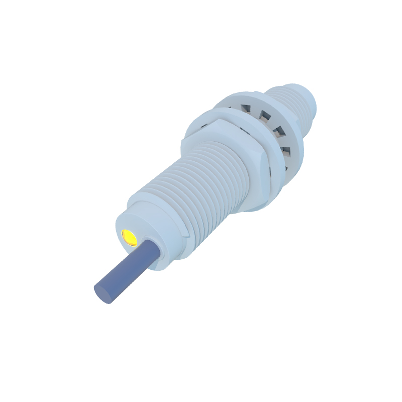
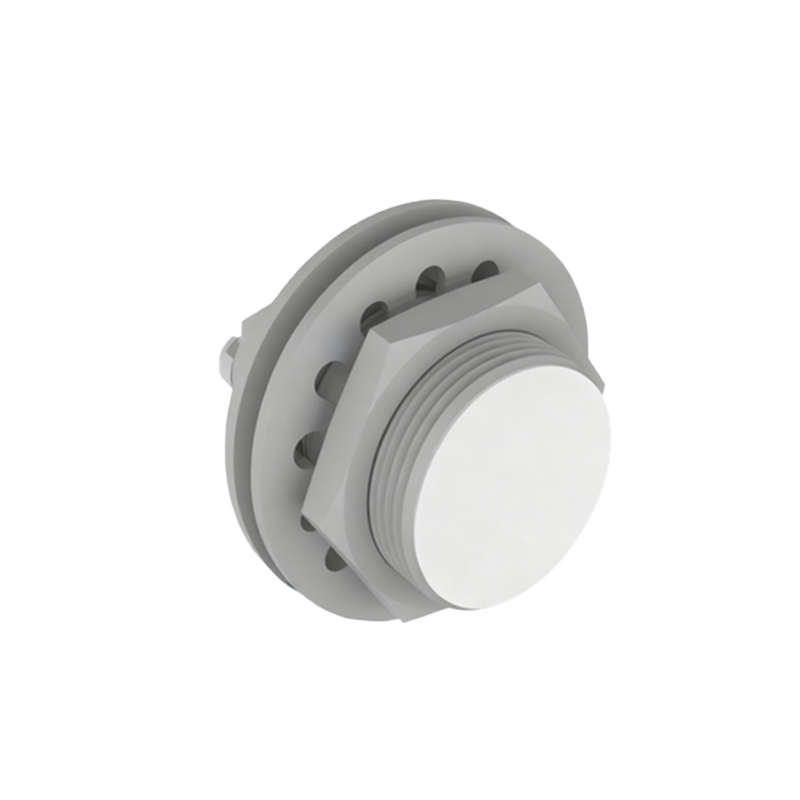
Proximity sensors are indispensable components in modern industrial automation, robotics, and machinery systems. Understanding their model codes and interpreting their meaning diagrams is crucial for proper selection, installation, and troubleshooting. This guide delves into the structure of common proximity sensor model numbers and provides a detailed breakdown of standard meaning diagrams found in datasheets.
A typical proximity sensor model number is not a random string of characters; it is a coded language that conveys vital specifications. For instance, consider a model like E2E-X5D1-N. Breaking this down: 'E2E' often indicates the series or product family from a specific manufacturer, in this case, a cylindrical shielded inductive sensor. 'X5' might denote the sensing distance, here 5mm. 'D1' could specify the output type (e.g., NPN normally open) and the connection method. 'N' frequently represents the electrical specifications, such as a DC 3-wire type. Different manufacturers have their own coding systems, but the logic remains similar: series, sensing distance, output configuration, housing size, connection type, and special features are encoded sequentially. A key part of the diagram accompanying this is the "Model Number Structure" chart, which visually maps each segment of the code to its technical meaning.
Beyond the model number, the meaning diagram—often called a functional diagram or outline drawing—is equally important. This diagram provides a visual and symbolic representation of the sensor's key characteristics. A standard meaning diagram includes several critical sections. First, the Sensing Characteristics Graph plots sensing distance versus factors like target material (steel, aluminum, copper) and temperature. It shows the reduction factor for non-ferrous metals, a vital parameter for application accuracy. Second, the Output Configuration Schematic uses standard electrical symbols (like transistors for NPN/PNP) to clearly show the wiring between the brown (V+), blue (V-), and black (output) wires, including the circuit logic (normally open/closed). Third, the Timing Chart illustrates the sensor's response time, output delay, and switching frequency, which are essential for high-speed automation cycles.
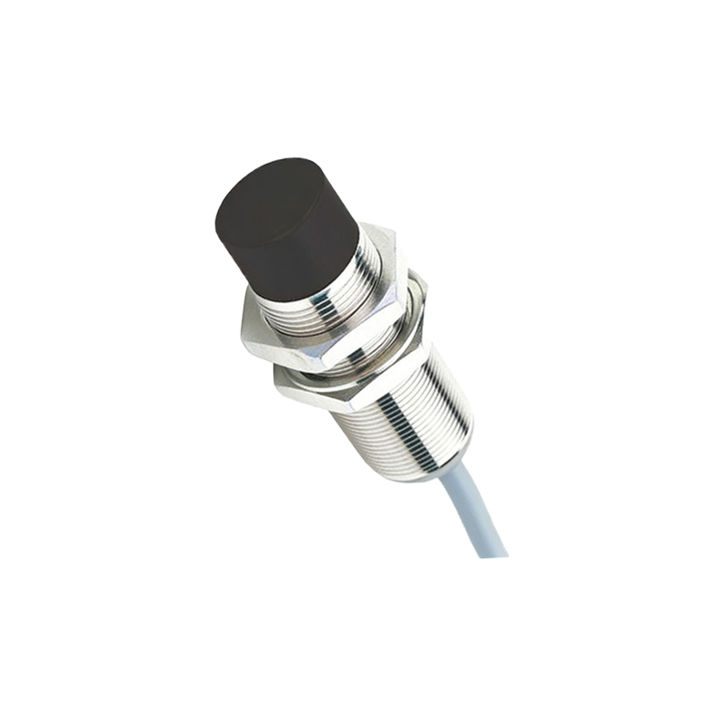
Another crucial part of the meaning diagram is the Installation and Clearance Diagram. This shows the required lateral and axial clearance between multiple sensors to prevent mutual interference, a common issue in dense mounting arrangements. It also indicates the effective sensing area, which is not always the entire face of the sensor. For capacitive sensors, a diagram often includes adjustment potentiometer symbols for sensitivity tuning. For ultrasonic sensors, the diagram details the beam angle and pattern.
When selecting a sensor, cross-referencing the model number with the meaning diagram prevents errors. For example, a model suffix 'M12' indicates an M12 connector, but the diagram will specify if it is a 3-pin or 4-pin variant and the pin assignment. Similarly, a code for 'IP67' protection is best understood with the diagram showing the sealing gasket location and housing material. Engineers must also pay attention to diagrams detailing hysteresis, the difference between the operating point and release point, as it affects system stability.
In conclusion, proficiency in deciphering proximity sensor model numbers and their accompanying meaning diagrams is a fundamental skill for electrical and automation engineers. This knowledge ensures optimal sensor selection for specific environmental conditions, target materials, and electrical interfaces, thereby enhancing system reliability and performance. Always consult the manufacturer's specific datasheet, as coding conventions and diagram symbols can vary, but the core principles of decoding series, range, output, and connection remain universally applicable across inductive, capacitive, and ultrasonic proximity sensor types.