In industrial automation and control systems, laser sensors play a critical role in precision measurement, detection, and positioning. Accurately interpreting their associated icons is essential for engineers, technicians, and operators to ensure correct installation, configuration, and troubleshooting. These standardized symbols, often found on device housings, datasheets, and control panel diagrams, convey vital information about the sensor's function, status, and interface at a glance.
One of the most fundamental icons is the simple laser beam symbol, typically represented by a straight line or a narrow, diverging set of lines emanating from a point source. This universal symbol indicates the device is a laser-based sensor. Often, this is accompanied by a wavelength specification icon, such as "650nm" or "905nm," which is crucial for safety and application compatibility. A red or infrared light wave pictogram might also be used.

Status indication icons are paramount for operational feedback. A steady "ON" or green LED indicator icon signifies normal operation and power supply. A blinking or flashing light symbol, however, often indicates a specific mode, such as teach-in mode for setting thresholds, or a warning condition like marginal signal strength. Icons for "Alarm" or "Fault" are usually represented by an exclamation mark within a triangle or a similar warning symbol, signaling an error that requires attention, such as a dirty lens, misalignment, or out-of-range target.
Output state icons are directly linked to the sensor's switching function. A "NO" (Normally Open) or "NC" (Normally Closed) contact symbol is standard, depicting the state of the output relay or transistor. This is frequently paired with a graphical representation of the sensing response: an icon showing an object breaking a beam for through-beam sensors, or an object reflecting a beam back to the source for retro-reflective or diffuse sensors. For analog output sensors, an icon representing a continuous signal or a graph with a rising/falling line is common.
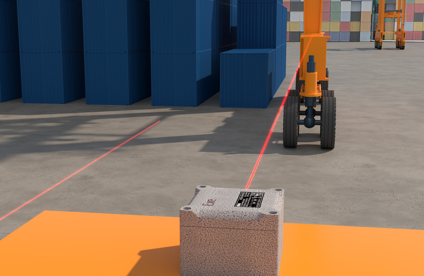
Connection and interface icons guide proper wiring. Symbols for "PWR" or "+V" and "GND" denote power supply terminals. Output terminals are often marked with "OUT," "Q," or specific labels like "PNP" or "NPN," accompanied by the standard electronic symbols for these transistor types. Some advanced sensors feature icons for communication interfaces, such as the stylized symbols for IO-Link, PROFINET, or EtherNet/IP, indicating digital data exchange capabilities.
Safety-related icons are non-negotiable. The mandatory laser safety warning—a black sunburst symbol inside a triangle with "LASER" text—is always present on Class 2 or higher laser devices. An "Eye" symbol with a slash warns against looking directly into the beam. Additional icons may indicate protection ratings, such as the IP (Ingress Protection) code (e.g., IP67 icon showing resistance to dust and water) or specific approvals like CE, UL, or ATEX for hazardous environments.
Understanding these icons streamlines system integration and maintenance. For instance, a diffuse reflective laser sensor might combine the basic laser symbol with an icon showing a beam hitting a nearby object and scattering back. A background suppression sensor icon might include a graphical hint of its ability to ignore objects beyond a set distance. Time-of-flight or distance-measuring sensors often incorporate a ruler or double-arrow icon alongside the laser symbol.
In conclusion, mastering the lexicon of laser sensor icons is a fundamental skill for electrical and automation professionals. These pictograms form a concise, international language that transcends textual manuals, enabling faster decision-making, reducing setup errors, and enhancing overall operational safety and efficiency in complex industrial settings. Always cross-reference the specific manufacturer's documentation, as minor symbolic variations can exist, but the core concepts remain consistently grounded in international engineering standards.